Table of Contents
Advertisement
Quick Links
CONTENTS
CS-C12ATP5 CU-C12ATP5
CS-C18ATP5 CU-C18ATPT5
CS-C24ATP5 CU-C24ATPT5
CS-C18ATP6 CU-C18ATPT6
CS-C24ATP6 CU-C24ATPT6
Page
2
5
15
17
18
19
21
23
27
© 2001 Matsushita Air-Conditioning Corp. Sdn. Bhd.
(183914D). All rights reserved. Unauthorized copying
and distribution is a violation of law.
Order No. MAC0112082C0
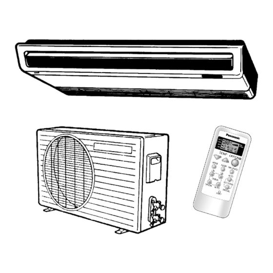
Room Air Conditioner
Page
38
39
41
45
46
47
48
49
50
Advertisement
Table of Contents
Troubleshooting

Related Manuals for Panasonic CS-C12ATP5


Summary of Contents for Panasonic CS-C12ATP5
-
Page 1: Table Of Contents
Order No. MAC0112082C0 Room Air Conditioner CS-C12ATP5 CU-C12ATP5 CS-C18ATP5 CU-C18ATPT5 CS-C24ATP5 CU-C24ATPT5 CS-C18ATP6 CU-C18ATPT6 CS-C24ATP6 CU-C24ATPT6 CONTENTS Page Page 1 Functions 10 Servicing Information 2 Product Specifications 11 Troubleshooting Guide 3 Dimensions 12 Technical Data 4 Refrigeration Cycle Diagram 13 Exploded View... -
Page 2: Functions
CS-C12ATP5 CU-C12ATP5 / CS-C18ATP5 CU-C18ATPT5 / CS-C24ATP5 CU-C24ATPT5 / CS-C18ATP6 CU-C18ATPT6 / CS-C24ATP6 CU-C24ATPT6 1 Functions Remote Control Transmitter AUTO SPEED COOL ON OFF TEMP OFF/ON MODE SLEEP FAN SPEED AUTO TIMER AIR SWING OFF/ON SET/C MANUAL RESET Remote Control... - Page 3 CS-C12ATP5 CU-C12ATP5 / CS-C18ATP5 CU-C18ATPT5 / CS-C24ATP5 CU-C24ATPT5 / CS-C18ATP6 CU-C18ATPT6 / CS-C24ATP6 CU-C24ATPT6 Indoor Unit Sensing The Room Temperature Air Circulation Operation Mode Room Temperature Sensor (thermistor) (Fan only operation) Low Fan Speed operation interlocked with the setting temp.
- Page 4 CS-C12ATP5 CU-C12ATP5 / CS-C18ATP5 CU-C18ATPT5 / CS-C24ATP5 CU-C24ATPT5 / CS-C18ATP6 CU-C18ATPT6 / CS-C24ATP6 CU-C24ATPT6 Outdoor Unit Overload Protector...
-
Page 5: Product Specifications
CS-C12ATP5 CU-C12ATP5 / CS-C18ATP5 CU-C18ATPT5 / CS-C24ATP5 CU-C24ATPT5 / CS-C18ATP6 CU-C18ATPT6 / CS-C24ATP6 CU-C24ATPT6 2 Product Specifications Unit CS-C12ATP5 CU-C12ATP5 Cooling Capacity 3.45; 3.45; 3.50 BTU/h 11,700; 11,700; 11,900 kcal/h 2,970; 2,970; 3,050 Moisture Removal Pint/h Power Source Phase Single 220;... - Page 6 CS-C12ATP5 CU-C12ATP5 / CS-C18ATP5 CU-C18ATPT5 / CS-C24ATP5 CU-C24ATPT5 / CS-C18ATP6 CU-C18ATPT6 / CS-C24ATP6 CU-C24ATPT6 Unit CS-C12ATP5 CU-C12ATP5 Air Circulation Type SIROCCO Propeller Fan Material STYLAC 181 AES + Glass Fiber 12% Motor Type Induction (4-poles) Induction (6-poles) Input 45.6 58.6...
- Page 7 CS-C12ATP5 CU-C12ATP5 / CS-C18ATP5 CU-C18ATPT5 / CS-C24ATP5 CU-C24ATPT5 / CS-C18ATP6 CU-C18ATPT6 / CS-C24ATP6 CU-C24ATPT6 Unit CS-C18ATP5 CU-C18ATPT5 Cooling Capacity 5.15; 5.20; 5.30 Btu/h 17,500; 17,700; 18,000 kcal/h 4,430; 4,470; 4,560 Moisture Removal Pint/h Power Source Phase Single 220; 230; 240...
- Page 8 CS-C12ATP5 CU-C12ATP5 / CS-C18ATP5 CU-C18ATPT5 / CS-C24ATP5 CU-C24ATPT5 / CS-C18ATP6 CU-C18ATPT6 / CS-C24ATP6 CU-C24ATPT6 Unit CS-C18ATP5 CU-C18ATPT5 Air Circulation Type SIROCCO Propeller Fan Material STYLAC 181 CE10G15 JSR Motor Type Induction (4-poles) Induction (4-poles) Input 66.00 136.8 (High) Rated Output...
- Page 9 CS-C12ATP5 CU-C12ATP5 / CS-C18ATP5 CU-C18ATPT5 / CS-C24ATP5 CU-C24ATPT5 / CS-C18ATP6 CU-C18ATPT6 / CS-C24ATP6 CU-C24ATPT6 Unit CS-C18ATP6 CU-C18ATPT6 Cooling Capacity 5.30 Btu/h 18,100 kcal/h 4,560 Moisture Removal Pint/h Power Source Phase Single Cycle Airflow Method OUTLET SIDE VIEW TOP VIEW INTAKE...
- Page 10 CS-C12ATP5 CU-C12ATP5 / CS-C18ATP5 CU-C18ATPT5 / CS-C24ATP5 CU-C24ATPT5 / CS-C18ATP6 CU-C18ATPT6 / CS-C24ATP6 CU-C24ATPT6 Unit CS-C18ATP6 CU-C18ATPT6 Air Circulation Type SIROCCO Propeller Fan Material STYLAC 181 CE10G15 JSR Motor Type Induction (4-poles) Induction (4-poles) Input 61.27 93.60 (High) Rated Output...
- Page 11 CS-C12ATP5 CU-C12ATP5 / CS-C18ATP5 CU-C18ATPT5 / CS-C24ATP5 CU-C24ATPT5 / CS-C18ATP6 CU-C18ATPT6 / CS-C24ATP6 CU-C24ATPT6 Unit CS-C24ATP5 CU-C24ATPT5 Cooling Capacity 6.30; 6.30; 6.35 Btu/h 21,500; 21,500; 21,600 kcal/h 5,420; 5,420; 5,440 Moisture Removal Pint/h Power Source Phase Single 220; 230; 240...
- Page 12 CS-C12ATP5 CU-C12ATP5 / CS-C18ATP5 CU-C18ATPT5 / CS-C24ATP5 CU-C24ATPT5 / CS-C18ATP6 CU-C18ATPT6 / CS-C24ATP6 CU-C24ATPT6 Unit CS-C24ATP5 CU-C24ATPT5 Air Circulation Type SIROCCO Propeller Fan Material STYLAC 181 CE10G15 JSR Motor Type Induction (4-poles) Induction (4-poles) Input 66.00 141.7 (High) Rated Output...
- Page 13 CS-C12ATP5 CU-C12ATP5 / CS-C18ATP5 CU-C18ATPT5 / CS-C24ATP5 CU-C24ATPT5 / CS-C18ATP6 CU-C18ATPT6 / CS-C24ATP6 CU-C24ATPT6 Unit CS-C24ATP6 CU-C24ATPT6 Cooling Capacity 6.45 Btu/h 22,200 kcal/h 5,550 Moisture Removal Pint/h Power Source Phase Single Cycle Airflow Method OUTLET SIDE VIEW TOP VIEW INTAKE...
- Page 14 CS-C12ATP5 CU-C12ATP5 / CS-C18ATP5 CU-C18ATPT5 / CS-C24ATP5 CU-C24ATPT5 / CS-C18ATP6 CU-C18ATPT6 / CS-C24ATP6 CU-C24ATPT6 Unit CS-C24ATP6 CU-C24ATPT6 Air Circulation Type SIROCCO Propeller Fan Material STYLAC 181 CE10G15 JSR Motor Type Induction (4-poles) Induction (4-poles) Input 61.27 108.3 (High) Rated Output...
-
Page 15: Dimensions
CS-C12ATP5 CU-C12ATP5 / CS-C18ATP5 CU-C18ATPT5 / CS-C24ATP5 CU-C24ATPT5 / CS-C18ATP6 CU-C18ATPT6 / CS-C24ATP6 CU-C24ATPT6 3 Dimensions... - Page 16 CS-C12ATP5 CU-C12ATP5 / CS-C18ATP5 CU-C18ATPT5 / CS-C24ATP5 CU-C24ATPT5 / CS-C18ATP6 CU-C18ATPT6 / CS-C24ATP6 CU-C24ATPT6...
-
Page 17: Refrigeration Cycle Diagram
CS-C12ATP5 CU-C12ATP5 / CS-C18ATP5 CU-C18ATPT5 / CS-C24ATP5 CU-C24ATPT5 / CS-C18ATP6 CU-C18ATPT6 / CS-C24ATP6 CU-C24ATPT6 4 Refrigeration Cycle Diagram... -
Page 18: Block Diagram
CS-C12ATP5 CU-C12ATP5 / CS-C18ATP5 CU-C18ATPT5 / CS-C24ATP5 CU-C24ATPT5 / CS-C18ATP6 CU-C18ATPT6 / CS-C24ATP6 CU-C24ATPT6 5 Block Diagram... -
Page 19: Wiring Diagram
CS-C12ATP5 CU-C12ATP5 / CS-C18ATP5 CU-C18ATPT5 / CS-C24ATP5 CU-C24ATPT5 / CS-C18ATP6 CU-C18ATPT6 / CS-C24ATP6 CU-C24ATPT6 6 Wiring Diagram... - Page 20 CS-C12ATP5 CU-C12ATP5 / CS-C18ATP5 CU-C18ATPT5 / CS-C24ATP5 CU-C24ATPT5 / CS-C18ATP6 CU-C18ATPT6 / CS-C24ATP6 CU-C24ATPT6...
-
Page 21: Operation Details
CS-C12ATP5 CU-C12ATP5 / CS-C18ATP5 CU-C18ATPT5 / CS-C24ATP5 CU-C24ATPT5 / CS-C18ATP6 CU-C18ATPT6 / CS-C24ATP6 CU-C24ATPT6 7 Operation Details 7.1. Cooling Mode Operation When selecting the Cooling (COOL) Mode Operation, the unit will operate according to the setting by the Remote Control and the operation is as the following. - Page 22 CS-C12ATP5 CU-C12ATP5 / CS-C18ATP5 CU-C18ATPT5 / CS-C24ATP5 CU-C24ATPT5 / CS-C18ATP6 CU-C18ATPT6 / CS-C24ATP6 CU-C24ATPT6 7.3. Cooling Mode with Sleep Mode Auto Operation When selecting the Cooling (COOL) combined with the Sleep Mode Auto Operation (SLEEP), the operation shows as the following.
-
Page 23: Operating Instructions
CS-C12ATP5 CU-C12ATP5 / CS-C18ATP5 CU-C18ATPT5 / CS-C24ATP5 CU-C24ATPT5 / CS-C18ATP6 CU-C18ATPT6 / CS-C24ATP6 CU-C24ATPT6 8 Operating Instructions SAFETY PRECAUTIONS Operation Precautions Installation Precautions Before operating, please read the following “Safety Precautions” carefully. Warning Warning To prevent personal injury, injury to others and This sign warns of death or serious injury. -
Page 24: Preparation Before Operation
CS-C12ATP5 CU-C12ATP5 / CS-C18ATP5 CU-C18ATPT5 / CS-C24ATP5 CU-C24ATPT5 / CS-C18ATP6 CU-C18ATPT6 / CS-C24ATP6 CU-C24ATPT6 How to Insert the Batteries NAME OF EACH PART 1 Signal Transmitter Remote Control 2 Operation Display Cooling Model AUTO AUTO SPEED SPEED COOL COOL Gently press the place marked OPEN and slide... -
Page 25: Convenience Operation
CS-C12ATP5 CU-C12ATP5 / CS-C18ATP5 CU-C18ATPT5 / CS-C24ATP5 CU-C24ATPT5 / CS-C18ATP6 CU-C18ATPT6 / CS-C24ATP6 CU-C24ATPT6 Setting the Fan Speed Setting the Horizontal Airflow Direction Operation Details • Press 4 to select:- – Low Fan Speed COOL – Cooling Operation – Medium Fan Speed •... -
Page 26: Helpful Information
CS-C12ATP5 CU-C12ATP5 / CS-C18ATP5 CU-C18ATPT5 / CS-C24ATP5 CU-C24ATPT5 / CS-C18ATP6 CU-C18ATPT6 / CS-C24ATP6 CU-C24ATPT6 HELPFUL INFORMATION ENERGY SAVING AND OPERATION Pre-season Inspection HINTS Clean the air filters, re-insert and operate the air Auto Operation conditioners. Setting the Temperature • Approximately 10% of electricity can be saved. -
Page 27: Installation Instructions
CS-C12ATP5 CU-C12ATP5 / CS-C18ATP5 CU-C18ATPT5 / CS-C24ATP5 CU-C24ATPT5 / CS-C18ATP6 CU-C18ATPT6 / CS-C24ATP6 CU-C24ATPT6 9 Installation Instructions Required tools for Installation Works 1. Philips screw driver 5. Spanner 9. Gas leak detector 13. Multimeter 2. Level gauge 6. Pipe cutter 10. - Page 28 CS-C12ATP5 CU-C12ATP5 / CS-C18ATP5 CU-C18ATPT5 / CS-C24ATP5 CU-C24ATPT5 / CS-C18ATP6 CU-C18ATPT6 / CS-C24ATP6 CU-C24ATPT6 1. The equipment must be earthed. It may cause electrical shock if grounding is not perfect. 2. Do not install the unit at place where leakage of flammable gas may occur. In case gas leaks and accumulates at surrounding of the unit, it may cause fire.
- Page 29 CS-C12ATP5 CU-C12ATP5 / CS-C18ATP5 CU-C18ATPT5 / CS-C24ATP5 CU-C24ATPT5 / CS-C18ATP6 CU-C18ATPT6 / CS-C24ATP6 CU-C24ATPT6 Installation Parts Provided Installation parts you should purchase* 1. Suspension bolts (M10 × 600...4 pcs.) 1. *Bushing-sleeve 2. Nut, washer (M10...16 pcs.) 2. *Sleeve 3. Spring washer (M10...8 pcs) 3.
- Page 30 CS-C12ATP5 CU-C12ATP5 / CS-C18ATP5 CU-C18ATPT5 / CS-C24ATP5 CU-C24ATPT5 / CS-C18ATP6 CU-C18ATPT6 / CS-C24ATP6 CU-C24ATPT6 9.2. INDOOR UNIT 9.2.1. SELECT THE BEST LOCATION (Refer to “Select the best location” section) 9.2.2. HOW TO FIX INSTALLATION PLATE Installation on the ceiling Installation on the wall •...
-
Page 31: Indoor Unit Installation
CS-C12ATP5 CU-C12ATP5 / CS-C18ATP5 CU-C18ATPT5 / CS-C24ATP5 CU-C24ATPT5 / CS-C18ATP6 CU-C18ATPT6 / CS-C24ATP6 CU-C24ATPT6 Installation on the floor 9.2.4. INDOOR UNIT INSTALLATION • Measure and mark the position for the floor brackets and the Piping hole. • Drill the hole for the anchor nut. -
Page 32: Piping And Drainage
CS-C12ATP5 CU-C12ATP5 / CS-C18ATP5 CU-C18ATPT5 / CS-C24ATP5 CU-C24ATPT5 / CS-C18ATP6 CU-C18ATPT6 / CS-C24ATP6 CU-C24ATPT6 (ii) Secure the Indoor unit onto the Installation bracket with 9.2.5. CONNECT THE CABLE TO THE four M8 bolts with washer. INDOOR UNIT • Engage the lower flange of the hanging bracket on the 1. - Page 33 CS-C12ATP5 CU-C12ATP5 / CS-C18ATP5 CU-C18ATPT5 / CS-C24ATP5 CU-C24ATPT5 / CS-C18ATP6 CU-C18ATPT6 / CS-C24ATP6 CU-C24ATPT6 2. For the Left Side Piping. 5. For the Left Bottom or Right Bottom Piping. <For the Left Rear or Right Rear Piping of Ceiling or Attach the Edge Protector onto the edge of the Knock- Wall Mounting>...
-
Page 34: Install The Outdoor Unit
CS-C12ATP5 CU-C12ATP5 / CS-C18ATP5 CU-C18ATPT5 / CS-C24ATP5 CU-C24ATPT5 / CS-C18ATP6 CU-C18ATPT6 / CS-C24ATP6 CU-C24ATPT6 9.3. OUTDOOR UNIT 9.3.1. SELECT THE BEST LOCATION (Refer to “Select the best location” section) 9.3.2. INSTALL THE OUTDOOR UNIT At the best location, start installation according to Connecting The Piping To Outdoor Unit Indoor/Outdoor Unit Installation Diagram. - Page 35 CS-C12ATP5 CU-C12ATP5 / CS-C18ATP5 CU-C18ATPT5 / CS-C24ATP5 CU-C24ATPT5 / CS-C18ATP6 CU-C18ATPT6 / CS-C24ATP6 CU-C24ATPT6 9.3.4. (a) EVACUATION OF THE EQUIPMENT (FOR EUROPE & OCEANIA DESTINATION) WHEN INSTALLING AN AIR CONDITIONER, BE SURE TO EVACUATE THE AIR INSIDE THE INDOOR UNIT AND PIPES in the following procedure.
- Page 36 CS-C12ATP5 CU-C12ATP5 / CS-C18ATP5 CU-C18ATPT5 / CS-C24ATP5 CU-C24ATPT5 / CS-C18ATP6 CU-C18ATPT6 / CS-C24ATP6 CU-C24ATPT6 2) Air Purging The air which contains a moisture is remaining in the Refrigeration cycle may cause a malfunction on the Compressor. 1. To purge the air, push the pin on the Gas side 3-way valve for three seconds using with a Hexagonal wrench and set it free for one minute.
- Page 37 CS-C12ATP5 CU-C12ATP5 / CS-C18ATP5 CU-C18ATPT5 / CS-C24ATP5 CU-C24ATPT5 / CS-C18ATP6 CU-C18ATPT6 / CS-C24ATP6 CU-C24ATPT6 In case of the Outdoor unit is installed upper position of the indoor unit. 1. Tape the Pipings, and Connecting cable from down to up. 2. From the pipings gathered by taping along the exterior wall and the trap is required to prevent water from entering the room.
-
Page 38: Servicing Information
CS-C12ATP5 CU-C12ATP5 / CS-C18ATP5 CU-C18ATPT5 / CS-C24ATP5 CU-C24ATPT5 / CS-C18ATP6 CU-C18ATPT6 / CS-C24ATP6 CU-C24ATPT6 10 Servicing Information Pump-Down Terminal • The thermostat will be switched ON (even if the room temperature is low) when the pump-down terminal is short-circuited (by using) alligator-type clips or a similar method), thus permitting easy pump-down when the unit is to be moved to another place. -
Page 39: Troubleshooting Guide
CS-C12ATP5 CU-C12ATP5 / CS-C18ATP5 CU-C18ATPT5 / CS-C24ATP5 CU-C24ATPT5 / CS-C18ATP6 CU-C18ATPT6 / CS-C24ATP6 CU-C24ATPT6 11 Troubleshooting Guide 11.1. Refrigeration cycle system In order to diagnose malfunctions, make sure that there are no electrical problems before inspecting the refrigeration cycle. Such problems include insufficient insulation, problem with the power source, malfunction of a compressor and a fan. -
Page 40: Diagnosis Methods Of A Malfunction Of A Compressor
CS-C12ATP5 CU-C12ATP5 / CS-C18ATP5 CU-C18ATPT5 / CS-C24ATP5 CU-C24ATPT5 / CS-C18ATP6 CU-C18ATPT6 / CS-C24ATP6 CU-C24ATPT6 11.1.1. Relationship between the condition of the air conditioner and pressure and electric current Cooling Mode Condition of the air conditoner Low Pressure High Pressure Electric current during operation... -
Page 41: Technical Data
CS-C12ATP5 CU-C12ATP5 / CS-C18ATP5 CU-C18ATPT5 / CS-C24ATP5 CU-C24ATPT5 / CS-C18ATP6 CU-C18ATPT6 / CS-C24ATP6 CU-C24ATPT6 12 Technical Data... - Page 42 CS-C12ATP5 CU-C12ATP5 / CS-C18ATP5 CU-C18ATPT5 / CS-C24ATP5 CU-C24ATPT5 / CS-C18ATP6 CU-C18ATPT6 / CS-C24ATP6 CU-C24ATPT6 240V Outdoor Temp. (°C) Indoor wet bulb temp. 17.0°C 3.47 2.63 1.19 3.24 2.52 1.28 3.02 2.43 1.37 2.74 2.30 1.48 19.0°C 3.50 1.30 19.5°C 3.81 2.76...
- Page 43 CS-C12ATP5 CU-C12ATP5 / CS-C18ATP5 CU-C18ATPT5 / CS-C24ATP5 CU-C24ATPT5 / CS-C18ATP6 CU-C18ATPT6 / CS-C24ATP6 CU-C24ATPT6 240V Outdoor Temp. (°C) Indoor wet bulb temp. 17.0°C 5.26 3.99 2.01 4.91 3.82 2.16 4.57 3.67 2.31 4.16 3.49 2.49 19.0°C 5.30 2.19 19.5°C 5.77 4.17...
- Page 44 CS-C12ATP5 CU-C12ATP5 / CS-C18ATP5 CU-C18ATPT5 / CS-C24ATP5 CU-C24ATPT5 / CS-C18ATP6 CU-C18ATPT6 / CS-C24ATP6 CU-C24ATPT6 220V Outdoor Temp. (°C) Indoor wet bulb temp. 17.0°C 5.26 3.99 1.90 4.91 3.82 2.04 4.57 3.67 2.18 4.16 3.49 2.35 19.0°C 5.30 2.07 19.5°C 5.77 4.17...
-
Page 45: Exploded View
CS-C12ATP5 CU-C12ATP5 / CS-C18ATP5 CU-C18ATPT5 / CS-C24ATP5 CU-C24ATPT5 / CS-C18ATP6 CU-C18ATPT6 / CS-C24ATP6 CU-C24ATPT6 13 Exploded View... -
Page 46: Replacement Parts List
CS-C12ATP5 CU-C12ATP5 / CS-C18ATP5 CU-C18ATPT5 / CS-C24ATP5 CU-C24ATPT5 / CS-C18ATP6 CU-C18ATPT6 / CS-C24ATP6 CU-C24ATPT6 14 Replacement Parts List <Model: CS-C12ATP / CS-C18ATP / CS-C24ATP> Ref NO. DESCRIPTION & NAME QTY. CS-C24ATP5 CS-C18ATP5 CS-C18ATP6 CS-C12ATP5 CS-C24ATP6 ← ← ← ← CHASSY COMPLETE CWD52K195B ←... -
Page 47: Exploded View
CS-C12ATP5 CU-C12ATP5 / CS-C18ATP5 CU-C18ATPT5 / CS-C24ATP5 CU-C24ATPT5 / CS-C18ATP6 CU-C18ATPT6 / CS-C24ATP6 CU-C24ATPT6 15 Exploded View... -
Page 48: Replacement Parts List
CS-C12ATP5 CU-C12ATP5 / CS-C18ATP5 CU-C18ATPT5 / CS-C24ATP5 CU-C24ATPT5 / CS-C18ATP6 CU-C18ATPT6 / CS-C24ATP6 CU-C24ATPT6 16 Replacement Parts List <Model: CU-C12ATP / CU-C18ATP / CU-C24ATP> DESCRIPTION & NAME QTY. CU-C24ATPT5 CU-C18ATPT5 CU-C18ATPT6 CU-C12ATP5 CU-C24ATPT6 ← CHASSY ASSY CWD50K514B CWD50K515B CWD50K548A CWD50K514B ←... -
Page 49: Electronic Parts List
CS-C12ATP5 CU-C12ATP5 / CS-C18ATP5 CU-C18ATPT5 / CS-C24ATP5 CU-C24ATPT5 / CS-C18ATP6 CU-C18ATPT6 / CS-C24ATP6 CU-C24ATPT6 17 Electronic Parts List CWA73802 SYMBOL DESCRIPTION & NAME PART NO. BUZZER A48039 DIODE A3154RA15-01KB DIODE BRIDGE A54CS1VB20E FUSE FUSE XBA2C20TR0 INTEGRATED CIRCUIT A52MN15481Y INTEGRATED CIRCUIT... -
Page 50: Electronic Circuit Diagram
CS-C12ATP5 CU-C12ATP5 / CS-C18ATP5 CU-C18ATPT5 / CS-C24ATP5 CU-C24ATPT5 / CS-C18ATP6 CU-C18ATPT6 / CS-C24ATP6 CU-C24ATPT6 18 Electronic Circuit Diagram • CS-C12ATP / CU-C12ATP SCHEMATIC DIAGRAM 1/3 POWER 2kHz OUTPUT Ø1 4kHz OUTPUT 512kHz Ø0 Ø0 74HC4060P AC SINGLE PHASE FREQUENCY 240/220 50Hz... - Page 51 CS-C12ATP5 CU-C12ATP5 / CS-C18ATP5 CU-C18ATPT5 / CS-C24ATP5 CU-C24ATPT5 / CS-C18ATP6 CU-C18ATPT6 / CS-C24ATP6 CU-C24ATPT6 SCHEMATIC DIAGRAM 2/3 ELECTRONIC CIRCUIT 6.34Ω PUMP 0.01µ 100k – NH2(B) 22µ (SU) 2kHz NH4(W) – 1µ CN-TH (SU) RD6.2EL2 2SC1740S 4.7k RESET SIGNAL GENERATION 16.2k 10µ...
- Page 52 CS-C12ATP5 CU-C12ATP5 / CS-C18ATP5 CU-C18ATPT5 / CS-C24ATP5 CU-C24ATPT5 / CS-C18ATP6 CU-C18ATPT6 / CS-C24ATP6 CU-C24ATPT6 SCHEMATIC DIAGRAM 3/3 INTAKE AIR TEMP SENSOR (20kΩ 3950) Fig. 1 HEAT EXCHANGER TEMP SENSOR (15kΩ 3950) FORCED OPERATION SWITCH RECEIVER BROWN BROWN 6.3V 10µ 4300P CN-RCV –...
- Page 53 CS-C12ATP5 CU-C12ATP5 / CS-C18ATP5 CU-C18ATPT5 / CS-C24ATP5 CU-C24ATPT5 / CS-C18ATP6 CU-C18ATPT6 / CS-C24ATP6 CU-C24ATPT6 • CS-C18ATP / CU-C18ATPT • CS-C24ATP / CU-C24ATPT SCHEMATIC DIAGRAM 1/3 POWER 2kHz OUTPUT Ø1 4kHz OUTPUT 512kHz Ø0 Ø0 74HC4060P AC SINGLE PHASE FREQUENCY 240/220 50Hz...
- Page 54 CS-C12ATP5 CU-C12ATP5 / CS-C18ATP5 CU-C18ATPT5 / CS-C24ATP5 CU-C24ATPT5 / CS-C18ATP6 CU-C18ATPT6 / CS-C24ATP6 CU-C24ATPT6 SCHEMATIC DIAGRAM 2/3 ELECTRONIC CIRCUIT 6.34Ω PUMP 0.01µ 100k – NH2(B) 22µ (SU) 2kHz NH4(W) – 1µ CN-TH (SU) RD6.2EL2 2SC1740S 4.7k RESET SIGNAL GENERATION 16.2k 10µ...
- Page 55 CS-C12ATP5 CU-C12ATP5 / CS-C18ATP5 CU-C18ATPT5 / CS-C24ATP5 CU-C24ATPT5 / CS-C18ATP6 CU-C18ATPT6 / CS-C24ATP6 CU-C24ATPT6 SCHEMATIC DIAGRAM 3/3 INTAKE AIR TEMP SENSOR (20kΩ 3950) Fig. 1 HEAT EXCHANGER TEMP SENSOR (15kΩ 3950) FORCED OPERATION SWITCH RECEIVER BROWN BROWN 6.3V 10µ 4300P CN-RCV –...
- Page 56 CS-C12ATP5 CU-C12ATP5 / CS-C18ATP5 CU-C18ATPT5 / CS-C24ATP5 CU-C24ATPT5 / CS-C18ATP6 CU-C18ATPT6 / CS-C24ATP6 CU-C24ATPT6 How to use electronic circuit diagram TIMER TABLE Test Mode Name Time (When test point Remarks Short-circuited) Time Delay Safety Control 2 min. 58 sec. 0 sec.
- Page 57 CS-C12ATP5 CU-C12ATP5 / CS-C18ATP5 CU-C18ATPT5 / CS-C24ATP5 CU-C24ATPT5 / CS-C18ATP6 CU-C18ATPT6 / CS-C24ATP6 CU-C24ATPT6 18.1. REMOTE CONTROL...
- Page 58 CS-C12ATP5 CU-C12ATP5 / CS-C18ATP5 CU-C18ATPT5 / CS-C24ATP5 CU-C24ATPT5 / CS-C18ATP6 CU-C18ATPT6 / CS-C24ATP6 CU-C24ATPT6 18.2. PRINT PATTERN INDOOR UNIT PRINTED CIRCUIT BOARD...
- Page 59 CS-C12ATP5 CU-C12ATP5 / CS-C18ATP5 CU-C18ATPT5 / CS-C24ATP5 CU-C24ATPT5 / CS-C18ATP6 CU-C18ATPT6 / CS-C24ATP6 CU-C24ATPT6 [MACC] Printed in Malaysia...