Table of Contents
Advertisement
Quick Links
Download this manual
See also:
Manual
Advertisement
Table of Contents

Related Manuals for Panasonic AJ-HPX3100G


Summary of Contents for Panasonic AJ-HPX3100G
-
Page 1: Operating Instructions
Operating Instructions Memory Card Camera-Recorder Model No. Before operating this product, please read the insructions carefully and save this manual for future use. ENGLISH FJ0910HO5025 -FJ Printed in Japan VQT3A79-5... -
Page 2: Read This First
RISK OF ELECTRIC SHOCK Model Number: AJ-HPX3100G DO NOT OPEN Trade Name: Panasonic Responsible Party: Panasonic Corporation of North America One Panasonic Way, Secaucus, NJ 07094 CAUTION: TO REDUCE THE RISK OF ELECTRIC SHOCK, Support contact: 1-800-524-1448 DO NOT REMOVE COVER (OR BACK). - Page 3 EMC NOTICE FOR THE PURCHASER/USER OF THE APPARATUS 1. Applicable standards and operating environment (AJ-HPX3100G) The apparatus is compliant with: standards EN55103-1 and EN55103-2, and electromagnetic environments E1, E2, E3, E4, and E5. 2. Pre-requisite conditions to achieving compliance with the above standards <1>...
-
Page 4: To Remove The Battery
To remove the battery Main Power Battery (Ni-Cd / Ni-MH / Li-ion Battery) To detach the battery, please proceed in the reverse order of the installation method described in this manual. (Refer to page 108 for the detail.) If a battery made by any other manufacturer is to be used, check the Operating Instructions accompanying the battery. Back-up Battery (Lithium Battery) For the removal of the battery for disposal at the end of its service life, please consult your dealer. -
Page 5: Table Of Contents
Contents Read this first! ..................2 General Features of Camera unit ..............9 Features of Recorder/player unit ............10 Features of the Input/Output unit ............12 Other features ................... 12 Dimensions drawing................13 Color TV Standard Settings (Settings for frame frequency)....14 System Configuration................ - Page 6 Assigning Functions to USER Buttons..........55 Selecting Audio Input Signals and Adjusting Recording Levels..57 Setting External Reference Signal and GENLOCK ......61 Setting Time Data ................62 Viewfinder Screen Status Displays ........... 75 Adjusting and setting the LCD monitor ..........87 Selection of video output signals ............
- Page 7 Index ..........................204 The SD card logo is a registered trademark. SDHC Logo is a trademark of SD-3C, LLC. MMC (Multi Media Card) is a registered trademark of Infineon Technologies AG. Microsoft and Windows are trademarks or registered trademarks of Microsoft Corporation in the United States and/or other countries.
- Page 8 General Attention Adjust the following two settings when using the unit for the first time. The unit is a solid CCD camera-recorder integrating 2/3-inch 2.2-megapixel components that support interlaced/progressive drive (reading all pixels) and record/playback that supports the compression format for AVC-Intra100, AVC-Intra50 and DVCPRO HD, DVCPRO50, DVCPRO and DV.
-
Page 9: Features Of Camera Unit
Features of Camera unit Multi-format DRS (Dynamic Range Stretcher) function By applying the interlace drive/progressive drive With this function, the dynamic range of high brightness (reading all pixels) to the 2.2-mega pixel CCD, the unit areas that may be skipped with white blanks in an supports a variety of recording methods. -
Page 10: Features Of Recorder/Player Unit
Features of Recorder/player unit Multiple Slots HD: Format AVC-I 100/AVC-I 50/DVCPRO HD AJ-HPX3100 is equipped with 2 slots for P2 cards. 2 SD: Format DVCPRO50/DVCPRO/DV cards may be inserted in these slots for continuous Recorded video is compressed through a component recording. - Page 11 [Updating the Firmware incorporated into the unit] (page 199) For the latest information not available in the operating Instructions, visit the P2 Support Desk at the following Web sites. http://pro-av.panasonic.net/ General: Features of Recorder/player unit...
-
Page 12: Features Of The Input/Output Unit
Features of the Input/Output unit Independent Dual HD SDI output equipped as Confirmation of return video signals standard With the viewfinder, you can check the return video signal (analog HD-Y signal) supplied to the GENLOCK The HD SDI signals output from the SDI OUT connector IN connector of this unit or the HD SDI signal input to and the MON OUT connector are each independent. -
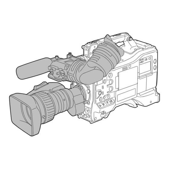
Page 13: Dimensions Drawing
Dimensions drawing General: Dimensions drawing... -
Page 14: Color Tv Standard Settings (Settings For Frame Frequency)
Color TV Standard Settings (Settings for frame frequency) The unit is delivered with the color TV standard not yet specified. To revise the settings for frame frequency according to the preferred standard, refer to the procedures described below. After connecting the unit to the power supply Move the arrow ( ) to YES and press the JOG and then turning on the power, press the dial button. -
Page 15: System Configuration
For the latest information on P2 cards and SD memory cards not available in the operating Instructions, visit the P2 Support Desk at the following Web sites. http://pro-av.panasonic.net/ General: System Configuration... -
Page 16: Power Supply And Accessory Mounting Section
Parts and their Functions Lens cable/microphone cable clamp POWER switch This clamp secures the lens and microphone cables. Used to turn on/off the power. [Mounting the Lens and Performing the Flange Back and White Shading Adjustments] (page 111) Battery mount A battery pack from Anton/Bauer is mounted here. - Page 17 VF connector (20 Pin) Installs the viewfinder (AJ-HVF21KG, AJ-CVF100G, which are optional). [Viewfinder] (page 30) Please be aware that when the SYSTEM MODE is set at 480/59.94i or 576/50i the image quality displayed on the viewfinder screen, and the image quality actually recorded and output from this unit will be different.
-
Page 18: Audio (Input) Function Section
AUDIO IN (audio input selector) switch MIC IN (microphone input) jack (XLR, 5-pin) Use this switch to select the signals recorded through A microphone (optional accessory) is connected here. Audio Channels 1 - 4. Power for the microphone comes from this jack. A remote microphone may be connected. - Page 19 Microphone input +48V ON/OFF switch This is the ON/OFF switch providing power to the microphone connected to the 5.AUDIO IN CH1/3 / CH2/ 4 (audio input channel 1/3 / 2/4) connector. Provides +48 V to the microphone. Does not provide +48 V to the microphone. If the REAR MIC POWER menu option is not set to “ON”...
-
Page 20: Audio (Output) Function Section
AUDIO OUT connector (XLR, 5-pin) Speakers This connector outputs audio signals recorded on The speakers output EE sound during recording, and Channels 1/2 or 3/4. reproduced sound during playback. Output signals are selected with the 11.MONITOR The speakers emit an alarm sound when the warning SELECT (audio channel) CH1/2 / CH3/4 selector switch. -
Page 21: Shooting And Recording/Playback Functions Section
SHUTTER switch CC FILTER/ND FILTER (filter switching) Used to enable or disable the electronic shutter. controls These are used to select the filter in accordance with the Electronic shutter disabled. subject’s brightness and color temperature. Electronic shutter enabled. Used to change the speed of the electronic CC FILTER knob (outside, large diameter) A : 3200K B : 4300K... - Page 22 PLAY and REW lamps Use of Panasonic’s SD memory cards and miniSD/ blinking. microSD cards is recommended. Be sure to format If this button is pressed when playback is paused, the cards using camera-recorder.
- Page 23 BUSY (operation mode display) lamp OUTPUT/AUTO KNEE selector switch This lamp indicates the active status of the SD memory Used to select the video signals sent from the camera card. unit to the memory, viewfinder and video monitor. It stays illuminated when the card is active. CAM.
- Page 24 MON OUT (monitor output) connector This is the video output connector for the monitor. According to the MONITOR OUT MODE menu option, images independent of SDI OUT can be output. Also, with the menu settings, HD-SDI or down converted SD- SDI or VBS can be selected.
-
Page 25: Menu Operation Section
MENU button Used to turn on/off the menu. JOG dial button With the menu open, this button is used to navigate through menu pages, select options and specify values. [Setting Menu Options] (page 160) SD memory card insertion slot An SD memory card (optional accessory) is inserted here. -
Page 26: Time Code Section
DISPLAY (counter display selector) switch GENLOCK IN connector (BNC) Indications of the time code, CTL and user bits on the This connector is used to input a reference signal before counter of the display window depend on the positions the camera unit is gen-locked, or before the time code is of this switch and the 8.TCG (time code selector) switch. -
Page 27: Warning And Status Display Functions
Back tally lamp When the 2.BACK TALLY switch is set to [ON], the lamp behaves in the same way as the front tally lamp at the viewfinder. BACK TALLY switch This switch controls the action of the 1.back and 7.rear tally lamps. -
Page 28: Display Window Functions
P2 card/battery-remaining level indications Stays illuminated when the camera-recorder operates in SD mode (480-59.94i, 576-50i) and is set to 16:9 mode. Stays illuminated when the camera-recorder is in HD The bar indicates the remaining free space on each P2 card, mode (1080i). -
Page 29: Lcd Monitor
CURSOR and SET buttons The four triangular buttons are the CURSOR buttons, and the center rectangular one is the SET button. They are used to select a thumbnail and manipulate the thumbnail menu. [Manipulating Clips with Thumbnails] (page 118). EXIT/CANCEL button Used to return the display to the previous state when the thumbnail menu or the property screen is displayed. -
Page 30: Viewfinder
An HD viewfinder can be used with this unit. It is recommended to use the optional AJ-HVF21KG or AJ-CVF100G (59.94/50 Hz switching). Video seen through Mode HD viewfinder viewfinder Video from camera Playback Return video (HD-Y) HD-SDI input (HD) Video from camera Playback Return video (VBS) HD-SDI input (SD... - Page 31 Eyepiece If, when fitting a large lens, there is insufficient space between the top of the lens and the bottom of the viewfinder, the positions of the slide rails can be shifted upwards slightly Do not leave the eyepiece aimed at the sun. Doing so by repositioning the screws.
-
Page 32: P2 Cards
Recording and Playback P2 Cards Inserting P2 Cards Insert a P2 card into the P2 card slot until the EJECT button pops up. When using the camera-recorder for the first time, be sure to set the time data beforehand. On how the time data is set, see [Setting Time Data] (page 62). Turn on the POWER switch. - Page 33 Removing P2 Cards The P2 CARD ACCESS LEDs may be set to stay off using the menu option ACCESS LED. The menu item ACCESS Open the card slot cover. LED is found in the <OPTION MODE> screen on the Raise the EJECT button. SYSTEM SETTING page.
-
Page 34: How To Handle Data Recorded On P2 Cards
How to handle data recorded on P2 cards The P2 card is a semiconductor memory card that is used as the recording medium in the professional video production and broadcasting devices that make up the DVCPRO P2 Series. Since data recorded in the DVCPRO P2 format or AVC- Device:\ Intra are in a file format, they have excellent compatibility with PCs. -
Page 35: Basic Procedures
Basic Procedures This section describes the basic procedure for shooting and Switch Setting recording. Before you embark on a shoot, pre-inspect your system to ensure that it works properly. When a battery and P2 cards are installed, set the switches as detailed below, before starting to use your unit. - Page 36 White/Black balance adjustment to recording completion White/Black Balance Adjustment to Recording Completion For shooting, follow the steps below. Select a filter according to light conditions. Position the WHITE BAL switch to [A] or [B]. When the white or black balance is not saved and you have no time to adjust the white balance: Position the WHITE BAL switch to [PRST].
-
Page 37: Normal Recording
Normal Recording REC button starts recording of video and sound on the P2 card. A cluster of data that consists of video and sound generated through a shooting action, together with such added information as meta data, is called a “clip”. Normal Recording and Native Recording In the unit, the camera’s recording method is selectable between the Native recording method with the frame rate... -
Page 38: Pre-Recording Function
PRE-RECORDING function The internal memory of your unit is capable of storing several seconds of video and sound data coming from the camera. This capability can be used to record video and sound several seconds before either the REC button is After recording is stopped, the “P-REC”... -
Page 39: Loop Recording
Loop Recording When two P2 card slots contain cards, this function allows the target P2 card to be switched in order. Even when the When the LOOP REC capability is used, each P2 card must free space of a P2 card is used up, this function continues have at least one minute of free space. - Page 40 Shooting procedures when INTERVAL REC is ON To stop the Interval recording mode Following basic operations of shooting and When INTERVAL REC HOLD is set to “OFF”, the mode recording according to “Basic Procedures”, returns to ordinary recording mode if the POWER switch of lock the camera securely.
- Page 41 Shooting procedures for the ONE SHOT mode of During INTERVAL REC mode general notes INTERVAL REC Interval recording does not record audio. During interval recording, all operation buttons other than Following basic operations of shooting and STOP (REW, FF, PLAY/PAUSE) are disabled. recording according to “Basic Procedures”, lock the camera securely.
-
Page 42: One Clip Rec Function
ONE CLIP REC Function This function compiles multiple recordings into a combined Exiting ONE CLIP REC mode clip and does not isolate single recordings (from REC START to STOP) to single clips. Set the ONE CLIP REC MODE item to “OFF” in the Menu. REC Start REC Start REC Start... - Page 43 (present as of Oct 2010). Refer to the P2 support page from the following web site for the most recent information on software that has been confirmed to work with these types of clips. http://pro-av.panasonic.net/ Recording and Playback: ONE CLIP REC Function...
-
Page 44: Recording Review Function
Recording Review Function When recording is paused, pressing the RET button automatically locates the last two seconds of video just recorded, and the viewfinder provides video playback. After playback, the camera-recorder is again ready to start recording. The picture location/playback duration can be increased to up to 10 seconds by continuously pressing the RET button. -
Page 45: Normal And Variable Speed Playback
Normal and Variable Speed Playback The PLAY/PAUSE button provides monochrome playback When playback is paused, the REW button locates the through the viewfinder and color playback on the LCD beginning of the current clip while maintaining the pause monitor. A color video monitor connected to the SDI OUT or mode. -
Page 46: Shot Mark Function
Shot Mark Function A shot mark is added to the thumbnail of a clip to distinguish Shot marks may also be added or erased using clip that clip from others. With the LCD monitor, only clips that thumbnails. have shot marks can be viewed and/or played back. [Shot Mark] (page 123) Adding Shot Marks When the color bar is output or the unit is in LOOP REC... -
Page 47: Multi Format
Multi Format Video system and Recording format The unit uses an interlace/progressive scan (reading all pixels) switchable type CCD. With combinations of the SYSTEM MODE and CAMERA MODE menu options, you can select a video system from among 12 types including HD (1080i) and SD. When selecting “SDI” on the REC SIGNAL menu option, you can record external signals input from the SDI IN connector. - Page 48 Recording formats and output connector signal formats The table below shows the formats used to record signals from the CCD and externally input signals along with the formats for signals output from the output connectors. Recording and output status OUTPUT OUTPUT Recording HD SDI (1080)
-
Page 49: Adjusting The White Balance And Black Balance
To record high-quality video with the unit, the black and white balances must be adjusted according to conditions. For higher quality, it is recommended that the adjustments should be made in this order AWB (white balance adjustment) ABB (black balance adjustment) AWB (white balance adjustment). - Page 50 Detection area for the white balance Retaining white balances The detection area for the white balance is selectable Each value in memory is retained even if the camera- recorder is turned off; it will not be lost until the white between 90%, 50% and 25%, using the menu option AWB AREA.
-
Page 51: Setting Color Temperature Manually
Setting Color Temperature Manually The white balance can be manually adjusted by setting the color temperature. Manual color temperature settings can be performed for each of the WHITE BAL switch positions: PRST, A and B. The color temperature is set using the menu options COLOR TEMP PRE, AWB A TEMP, and AWB B TEMP. -
Page 52: Adjusting The Black Balance
Adjusting the Black Balance The black balance must be adjusted when: You use your unit the first time; Ensure that the lens connector is connected and the Your unit has not been used for some time; lens iris is CLOSE. The ambient temperature has changed substantially;... -
Page 53: Setting The Electronic Shutter
Setting the Electronic Shutter This section provides a description of the electronic shutter, together with setting and handling directions. Shutter Modes The table below lists the shutter modes in which the unit’s electronic shutter can be used as well as the shutter speeds which can be selected. -
Page 54: Setting The Shutter Mode And Speed
Setting the Shutter Mode and Speed The shutter speed in any shutter mode is set using the SHUTTER switch. Press the SHUTTER switch, positioned at In SYNCHRO SCAN mode, shutter speed can be switched [ON], towards [SEL]. easily, using the SYNCHRO SCAN ADJUSTMENT switches (+/–) on the side panel. -
Page 55: Assigning Functions To User Buttons
Assigning Functions to USER Buttons The USER MAIN SW, USER1 SW , USER2 SW, SHOT “+3”. You can select the BLACK GAMMA MARK SW (USER3 SW) and TEXT MEMO SW (USER4 menu option from either the <LOW SW) buttons can be assigned user-selected functions. SETTING>... -
Page 56: Setting The Switchover Of User Sw Gain
channel 1 or audio channel 3 (you can switch MODE> screen on the SYSTEM SETTING with the VR SELECT menu option on the page. <MIC/AUDIO> screen of the MAIN : Function to add a shot mark when you press, OPERATION page) is assigned. and delete the mark when you press again is Pressing the button switches the input signal assigned. -
Page 57: Selecting Audio Input Signals And Adjusting Recording Levels
Selecting Audio Input Signals and Adjusting Recording Levels AJ-HPX3100 supports independent 4-channel sound recording in any recording format. When the AUDIO SELECT CH1/3 / CH2/4 switches are set to [AUTO], the recording level of audio channel 1/2 (3/4 with the menu settings) is automatically adjusted. -
Page 58: Recording Level Adjustment
Recording level adjustment You can select the recording level adjustment method from Audio level adjustment menu among three methods, the adjustment control/adjustment Select CH1/2 on the VR SELECT menu option with menu options/automatic adjustment. With the VR Select menu option, select the two channels, CH1/2 or CH3/4, to assign to the adjustment controls. - Page 59 Adjustment with AUDIO LEVEL CH1/3 / CH2/4 knobs Adjust the AUDIO LEVEL CH1/3 / CH2/4 knobs while looking at the audio channel level meter in the display window, or the audio level meter display in the LCD monitor. Also when the bar at the highest level (0dB) is passed, the OVER display lights up to indicate that the input volume is too great.
- Page 60 Selection table of adjustment methods When selecting “CH1/2” with the VR SELECT menu option AUDIO SELECT CH1/3 switch AUTO LEVEL CH3 menu item Adjustment methods Adjustment methods AUDIO SELECT CH2/4 switch AUTO LEVEL CH4 menu item Manual adjustment with Manual adjustment with the the adjustment controls LVL CONTROL CH3 menu option, LVL CONTROL CH4...
-
Page 61: Setting External Reference Signal And Genlock
Locking video signal to external reference signal You can lock the video signals output from this unit to a reference signal provided externally. The sub-carrier of the composite signals of this unit is not This unit can receive external reference signals from the locked to the sub-carrier of the reference signal. -
Page 62: Setting Time Data
Setting Time Data This unit provides time codes, user bits, and day-hour (real time) data as time data, and they are recorded in frames synchronous with images, and are also recorded as data for clip metadata files. It also includes a CTL counter and camera ID. Description of time data Time code CTL counter... - Page 63 Recording time code and user bits The number of frames for TC varies with the settings for the input signal, system mode, and camera mode as follows. Recording SYSTEM frame VITC LTC UB VITC UB SIGNAL MODE MODE As per the TC As per the TC As per the mode...
- Page 64 Setting of the User bits LTC UB is selected with the UB MODE menu option, and VITC UB is selected with the VITC UB MODE menu option. Position the TCG switch at [SET]. You can select each menu option from the <TC/UB> screen When the left digit starts blinking you can change the of the MAIN OPERATION page.
- Page 65 The frame rate information of user bits in Native recording is Frame rate information as follows. The frame rate and video pull-down menu are linked to the time code and user bits as follows: REC START/STOP mark Updated frame information/ Camera recording mode Effective frame Fixed value...
- Page 66 Setting the Internal Clock’s Date and Time Position the DISPLAY switch at [UB]. Area Area Greenwich – Kwajalein Press the HOLD button to display a date in the – display window. Central Europe – Midway Island Position the TCG switch at [SET]. –...
-
Page 67: Setting The Time Code
Setting the Time Code Regeneration function using REC REVIEW Position the DISPLAY switch at [TC]. If the menu option FIRST REC TC is set to PRESET, if the Position the TCG switch at [SET]. time code has been set or reset, or if the time code has been switched from free run to Rec run, it is possible to Set the menu option TC MODE to “DF”... -
Page 68: Externally Locking The Time Code
Externally Locking the Time Code The unit’s internal time code generator can be locked to an In the unit, there is a video signal delay in the camera, which external generator. In addition, the external time code is required or the process of converting video images taken generator can be locked to the unit’s internal generator. - Page 69 Example 4: When the unit and an external device are locked to the When the unit and an external device are locked to the external time code generator and when several units of external time code generator, which is connected the camera are connected in a cascade configuration.
- Page 70 Example 5: Example 6: When an external device is locked to the time code When an external device is locked to the time code generator of the unit. generator of camera-recorder, which is connected in a cascade configuration. Reference video signal To be connected if necessary To be connected if necessary 1st unit...
- Page 71 To externally lock the time code Cautions in switching the power source from battery to external power supply Follow the steps below. Connect the DC IN socket with the external power supply Turn on the POWER switch. before removing the battery pack, in order to keep the time code generator energised.
-
Page 72: Providing An Id To The Camera
Providing an ID to the Camera The camera ID is specified through the <CAMERA ID> screen. The ID can include up to 10 alphanumeric When the menu option CAMERA ID is set to “BAR”, the characters, symbols, and/or spaces. camera ID is recorded together with color bar signals. The menu item CAMERA ID is found in the <VF INDICATOR>... -
Page 73: Setting Umid Information
Setting UMID Information The unit supports UMID (Unique Material Identifier) metadata. You need to specify as UMID information the To exit the menu, press the MENU button. country where you live (using up to three characters), organisation or company (up to four characters) and user name (up to four characters). -
Page 74: Ctl Count Setting And Display
CTL Count Setting and Display By setting the DISPLAY switch to “CTL”, CTL count is The playback order of clips is altered when either of the displayed on the time count indication of the LCD display following occurs: window. Clips are deleted, copied or restored, or the P2 card is The CTL count is displayed in ±12 hours with non-drop- formatted. -
Page 75: Viewfinder Screen Status Displays
In addition to video images, the viewfinder displays lamps and text that indicate the settings and operating status of the unit, together with messages, a center marker, a safety zone marker and the camera ID. Lamps in the Viewfinder Screen Abnormal Operating Status Warning Lamp This lamp comes on when the unit is in any of the abnormal operating statuses specified through the... -
Page 76: Selecting Viewfinder Display Information
Selecting Viewfinder Display Information To select the information items you want to have displayed in the viewfinder screen, go to the <VF INDICATOR> screens from the VF page, and turn on or off the appropriate options, or specify desired values. For directions on setting the options, see [Setting Menu Options] (page 160). - Page 77 Information Item Indication Status 1. System mode This indicates the mode that the unit operates in. 1080-59.9i 1080-59.94 interlace mode 1080-50i 1080-50 interlace mode 480-59.9i 480-59.94 interlace mode 576-50i 576-50 interlace mode 2. Camera mode This indicates the video system when signals output from CCD are recorded on a P2 card or output as video signals.
- Page 78 Information Item Indication Status 10. GAIN switch LOW/MID/HIGH Value set for the master gain assignment –6 to 30 Example: LOW: 0 information (during S.GAIN 30/36/42 Gain value to which S.GAIN and DS.GAIN are assigned MODE CHECK) DS.GAIN 6 /10 /12 / These are displayed only during MODE CHCK.
- Page 79 Information Item Indication Status 12. User button functions User buttons disabled. UM: USER MAIN S.GAIN dB/OFF Selected S.GAIN DS.GAIN /OFF Selected DS.GAIN button S.IRIS ON/OFF Whether S.IRIS is ON or OFF. U1: USER1 button I.OVR ON/OFF Iris override can be set (the IRIS OVERRIDE setting is ON). U2: USER2 button S.BLK –...
- Page 80 Information Item Indication Status 13. System information SYSTEM ERROR- and warnings TURN POWER OFF P2 card has been removed while being accessed (recorded, played back, or formatted), and subsequent operation is disabled. CARD ERR An error has occurred while recording data to or playing data from a P2 card. In the actual indication the is replaced by the slot number of the P2 card that triggered the error.
- Page 81 Information Item Indication Status 20. WHITE BAL switch WHITE BAL switch positioned at [A]. position WHITE BAL switch positioned at [B]. WHITE BAL switch positioned at [PRST]. ATW mode is set. However it flashes when intensity and color are outside the operation range 21.
- Page 82 Displays in mode check only Display screens and menu options Status when displayed Displays menu options that become !LED lighting factors. !LED screen Indications selected through the menu option !LED are marked with [ ! ]. Indications which may activate the !LED are marked with [ GAIN (0 dB) Gain status DS.GAIN...
- Page 83 Display screen Indication Status Displays the CAC active status and information. CAC INFO Screen CAC CONT Displays the CAC operation mode as ON/STOP/OFF. CAC CONTROL in <CAC ADJ> is set to “ON”, and CAC is operating. STOP: “ON” is selected in the menu, but data or lens conditions stop CAC from operating.
- Page 84 Indications Available in the Viewfinder Screen Selectable Provided when between on and the appropriate Provided during Provided during Selectable off through menu status is MODE CHECK* playback options encountered. 1. System mode – – 2. Camera mode – – 3. REC FORMAT –...
- Page 85 Display Modes and Setting Changes/adjustment Result Messages The messages that appear on the viewfinder screen to indicate changes to settings and adjustment results may be limited, or set not to appear, through the menu option DISP MODE. This menu option can be found in the <VF DISPLAY>...
-
Page 86: Setting The Marker Displays
Setting the Marker Displays The center, safety zone, safety zone area and frame markers may be set to ON or OFF, along with specifications The indication MKR:A at the upper right of the screen shows of the marker types. To set and select markers, go to the the current indication status. -
Page 87: Adjusting And Setting The Lcd Monitor
Adjusting and setting the LCD monitor Using the LCD Monitor Through the menu option VF/LCD CHAR, specify whether or not the LCD should display Turn on the POWER switch of the unit. the same characters as the viewfinder. The menu item VF/LCD CHAR is found in the Slide the OPEN button in the arrow <OUTPUT SEL>... -
Page 88: Selection Of Video Output Signals
Selection of video output signals The unit employs the SDI OUT connector and the MON OUT connector as connectors for outputting video signals. Settings of signals output from SDI OUT connector The type of output signal from the SDI OUT connector is in accordance with the SYSTEM MODE item. -
Page 89: Settings Of Signals Output From Mon Out Connector
Settings of signals output from MON OUT connector The MON OUT connector outputs HD SDI signals, down- converted SD SDI signals, and analog signals. In the MONITOR OUT item, set the video signal output from the MON OUT connector. The MONITOR OUT item can be selected from the <OUTPUT SEL>... -
Page 90: Handling Data
Handling data Set data file configuration The unit employs 6 sets for the file data area. For menu items that can be read from or stored in the respective areas, refer to [Menu] (page 158) FACTORY data: The area for storing factory settings. Data cannot be revised with menu operations. -
Page 91: Handling Sd Memory Cards
Setting Data Using an SD memory card An SD memory card (optional accessory) can be used as a setup card that stores up to eight files of settings menu specifications. This data allows you to quickly reproduce an optimum state. <Cautions in using SD memory cards>... - Page 92 To format an SD memory card To exit the menu, press the MENU button. The settings menu disappears and the status of the unit is indicated at the top and bottom of the viewfinder SD memory cards may be formatted via the thumbnail screen. screen.
- Page 93 Press the JOG dial button. Press the JOG dial button to display the following message: This moves the cursor to the entry area, putting the unit in entry mode. The data will not be written if any of the following messages Turn the JOG dial button until a desired appears when the JOG dial button is pressed: character appears.
- Page 94 To exit the menu, press the MENU button. Press the JOG dial button to display the following message: The settings menu disappears and the status of the unit is indicated at the top and bottom of the viewfinder screen. It is possible to overwrite the setup file on the unit with a setup file from another device.
-
Page 95: How To Use The User Data
How to Use the User Data It is possible to transfer settings and other data to the user area of the internal memory of the unit. Turn the JOG dial button to move the cursor to This data allows you to quickly reproduce an optimum setup the option READ USER DATA. -
Page 96: How To Use Scene File Data
How to Use Scene File Data It is possible to write the settings data into the scene file area of the internal memory of the unit, or to read data written in Turn the JOG dial button to move the cursor to this area. - Page 97 To read settings data for scene files To return data for scene files to their defaults Navigate the menu to the <SCENE> screen. Navigate the menu to the <SCENE> screen. Turn the JOG dial button to move the cursor to Turn the JOG dial button to move the cursor to the option SCENE SEL.
- Page 98 To title settings data for scene files Press the JOG dial button. The following message is displayed. Navigate the menu to the <SCENE> screen. Turn the JOG dial button to move the cursor to the option [TITLE 1 - 4] for the appropriate scene file.
-
Page 99: Resetting Menu Option Settings To Defaults
Resetting Menu Option Settings to Defaults The menu settings can be reset to their defaults. To reset the settings to their defaults, select the menu option READ FACTORY DATA in the <INITIALIZE> screen, which is accessible from the FILE page. All settings will be reset to their defaults. - Page 100 To save the lens file into the built-in memory Press the JOG dial button again and turn it until the character to be set is displayed. Using the menu operations, open the <LENS When the button is turned, the character displayed is FILE>...
-
Page 101: To Read The Lens File From The Builtin Memory
Press the JOG dial button. Turn the JOG dial button to move the arrow (cursor) to YES, and press the JOG dial The following message is displayed. button. The current white shading correction value, the flare compensation value, and the RB gain offset correction value are stored in the built-in memory of the unit. - Page 102 To write in and read out the lens file to/from the SD memory card The contents of the eight lens files stored in the unit’s Saving lens files on the SD memory card internal memory can be saved onto an SD memory card as card files under a single title.
- Page 103 Loading lens files from the SD memory card Using menu operations, open the <LENS FILE CARD R/W> screen from the FILE page. Turn the JOG dial button to move the arrow (cursor) to the CARD FILE SELECT item. Press the JOG dial button and the card file number will flash.
-
Page 104: Chromatic Aberration Compensation (Cac)
The letters of CAC are indicated in the left top of the HJ22EX 7.6B IASE HJ22ex 7.6B IASE viewfinder screen. Visit our Web site at the address given below for details on additions or changes to lenses supporting CAC. http://pro-av.panasonic.net/ Adjustments and Settings for Recording Chromatic Aberration Compensation (CAC) - Page 105 For downloading, refer to the following URL. 2 --- at this time, data are recorded in available space of http://pro-av.panasonic.net/ the CAC FILE numbers on the unit. If “1” is selected, the data will overwrite the contents of CAC FILE No. 1.
- Page 106 To delete the CAC FILE from the unit To delete the CAC FILE from the SD memory card Open <CAC ADJ> from the MAINTENANCE Open <CAC FILE CARD READ> from the FILE page using the menu operation. page using the menu operation. The following screen is displayed.
- Page 107 If the following messages are displayed when the JOG dial When CAC FILE does not operate properly button is pressed, the data cannot be deleted. The following error messages are displayed in the viewfinder Error message Measures when CAC does not operate properly or CAC files cannot be DELETE NG Insert an SD memory card.
-
Page 108: Preparation Power Supply
Preparation Power Supply A battery pack or an external DC power supply can be used as AJ-HPX3100’s power supply. Using a Battery Pack Battery packs from the following manufacturers can be used: • Anton/Bauer • The type of the battery can be checked or changed through the viewfinder or menu screen on the monitor. -
Page 109: Mounting The Battery And Setting The Battery Type
Mounting the Battery and Setting the Battery Type Using an Anton/Bauer Battery Pack When using a V-mount type battery pack Mount the Anton/Bauer battery pack. Mount the V-mount adapter plate. Anton/Bauer Battery Pack Insert the battery and slide it in the direction of the arrow. -
Page 110: Use Of The External Dc Power Supply
Use of the external DC power supply Connect the external DC power supply to the DC IN socket on the unit. If both the battery pack and the external DC power supply are connected, the electric power is supplied from the external DC power supply. While the external DC power supply is used, the battery can be mounted and removed on/from the unit. -
Page 111: Mounting The Lens And Performing The Flange Back And White Shading Adjustments
Mounting the Lens Adjusting the Lens Flange Back If images are not clearly focused at both telephoto and wide- Raise the lens clamping lever and remove the angle positions during zoom operations, adjust the flange back (distance from the lens mounting surface to the image mount cap. - Page 112 Repeat Steps until the lens is in focus at Set the lens aperture control to manual, and both the telephoto and wide-angle positions. adjust it so that the zebra pattern covers the whole screen. Firmly tighten the F.f ring clamping screw. Check that the lens aperture is between F4 and F11.
- Page 113 When the lens has an extender, repeat steps to enable the extender function. The camera-recorder stores, as one lens file data item, two different correction values for the following: a lens with an extender, a lens with no extender. When making the white shading correction, make the adjustment while observing the R, G, and B waveforms in the horizontal and vertical directions with the waveform monitor.
-
Page 114: Preparing For Audio Input
Preparing for Audio Input Take the following steps to prepare the camera for connecting audio input devices. When Using the Front Microphone AJ-HPX3100 can be equipped with the AJ-MC900G stereo microphone kit (an extra-cost option). Connect the microphone cable to the MIC IN jack on the camera. -
Page 115: Mounting The Camera On A Tripod
When Using Audio Devices Connect the audio device to the AUDIO IN jack with the XLR cable. Set the AUDIO IN switch to [REAR] for the channel to which the XLR cable is connected. Set the LINE/MIC selector switch on the rear panel to [LINE]. -
Page 116: Attaching The Shoulder Strap
Attaching the Shoulder Strap To detach the shoulder strap, first open the hooks, then Shoulder Strap detach the strap. Make sure that the shoulder strap is securely attached. Press to open the hook. Attaching the Rain Cover When using the SHAN-RC700 Rain Cover Tighten the cord Secure with the surface fastener... -
Page 117: Attaching The F.audio Level Control Knob
Attaching the F.AUDIO LEVEL control Knob If you use the F.Audio Level control frequently, attach the F.Audio Knob accessory knob so that it can be easily operated. Level Control (Accessory) Remove the screw in the center of the F.Audio Level control, Screw and attach the accessory knob using the screw (included). -
Page 118: Manipulating Clips With Thumbnail Manipulations Overview
A clip is a data group that includes the images and voices Playback, delete, copy or restore the clip. created from one shooting session, together with additional Add or delete a shot mark and a text memo on the clip information such as text memos and meta data. -
Page 119: Thumbnail Screen
Thumbnail Screen Indicated when the camera-recorder is updating the screen or reading data. When Press the THUMBNAIL button to display the thumbnail the screen is being updated, the rotating icon screen on the LCD monitor. Pressing the THUMBNAIL button again returns the display to the regular display. When [Switching the Thumbnail Display] (page 122) switching is done from the regular screen display to the thumbnail screen display, all the clips will be displayed on... - Page 120 Clip Number The numbers set by the camera for all the clips recognised correctly by the P2 card. These numbers are allocated in chronological order, by shooting dates and times. If clips cannot be played because of different recording formats, they are displayed in red. This marker is displayed for defective clips, which may result from a variety of causes, e.g., powering-down during recording.
-
Page 121: Selecting Thumbnails
Selecting Thumbnails Playing back Clips Multiple thumbnails can be randomly selected in the thumbnail screen. Press the THUMBNAIL button. The thumbnail screen appears on the LCD monitor. Use the cursor buttons to move the pointer (yellow frame) to the desired clip and press Use the cursor buttons to move the pointer the SET button. -
Page 122: Switching The Thumbnail Display
Switching the Thumbnail Display Select THUMBNAIL from the thumbnail menu. Switch the thumbnail display by selecting one of the The display can be switched so that only those clips following items: matching the specified conditions are displayed in the thumbnail screen. Press the THUMBNAIL button. -
Page 123: Changing Thumbnails
Changing Thumbnails Shot Mark It is possible to replace thumbnails with images that include A shot mark can be added to a clip thumbnail to distinguish previously attached text memos while images are recorded this clip from the others. or played back. Press the THUMBNAIL button. - Page 124 Text Memo Playing back a clip at the position where a text memo is recorded During recording or playback, you can add text memos to clips. Text memos can be used to play back clips at some Press the THUMBNAIL button. point or break clips into chunks and copy the necessary The thumbnail screen appears on the LCD monitor.
- Page 125 Using a text memo to break a clip and copy the With the pointer located in the lower part, necessary portion move the pointer to the desired text memo number using the cursor right and left buttons Select a desired text memo in a clip by ).
-
Page 126: Deleting Clips
Deleting Clips Restoring Clips Restores clips that are defective as a result of sudden Press the THUMBNAIL button. powering-down during recording, or removal of the P2 card being accessed. The thumbnail screen appears on the LCD monitor. Use the cursor buttons to move the pointer Only those clips with yellow corrupt clip markers can be over the clip you want to delete and restored. -
Page 127: Reconnection Of Incomplete Clips
Reconnection of Incomplete Clips Press the THUMBNAIL MENU button and select OPERATION COPY from the Incomplete clips may be generated when clips recorded on thumbnail menu. multiple P2 cards (connected clips) are separately copied to Select Slot 1-2 or SD memory card as the different cards. -
Page 128: Setting Of Clip Meta Data
PC. Download the latest version of the P2 viewer Reading Clip Meta Data (metadata upload) from the following URL and install it to your PC. http://pro-av.panasonic.net/ Insert the SD memory card that contains the Regarding SD memory cards to be used, see <Cautions in Clip Meta Data (metadata upload file). - Page 129 While viewing the settings for the metadata, Displays the location of the frame (frame offset) and the size (height and width) of the image use the cursor buttons to move the pointer to selected as the thumbnail image. the desired option. Then, press the SET button.
- Page 130 Example of recording (DVCPRO HD) a clip on one P2 card: Selecting the USER CLIP NAME recording method REC start Recording pause Select META DATA USER CLIP NAME from the Recording duration = Approx. 7 min. thumbnail menu to select the recording method. Two options are available: TYPE1 and TYPE2.
-
Page 131: Formatting A P2 Card
Formatting a P2 Card Formatting SD memory cards SD memory cards can also be formatted from the thumbnail Press the THUMBNAIL button. screen. With an SD memory card inserted into the camera- recorder, perform the following operation: The thumbnail screen appears on the LCD monitor. Press the THUMBNAIL button. - Page 132 For the size of thumbnails displayed on one screen, either LARGE (3 2 thumbnails displayed) or The thumbnail display mode can be customised to suit your NORMAL (4 3 thumbnails displayed) can be preferences. selected. The factory default value is NORMAL. Press the THUMBNAIL button.
-
Page 133: Thumbnails
Properties Clip Meta Data Displays more detailed data about the clip. Use the The clip’s properties and the P2 card’s status are displayed. cursor buttons to move the pointer, and press the SET It is possible to edit and rewrite recorded clip metadata while button to check the detailed content. - Page 134 Contents of P2 Card Status Display Settings Deleting only the respective items of LOCATION From the thumbnail menu, select PROPERTY CARD (recording location data) in SHOOT is not possible. By STATUS. The following screen appears. setting ALTITUDE to empty, other LONGITUDE/ LATITUDE items are collectively deleted.
- Page 135 SD memory card Status Display The status display enables a confirmation of the SD memory card formatted condition, available memory capacity etc. From the thumbnail menu, select PROPERTY DEVICES SD CARD. SD STANDARD: Indicates that an SD memory card is formatted according to the SD/SDHC standard.
-
Page 136: Connection With External Device
Connection with external device Connection with a PC in the USB DEVICE mode By connecting AJ-HPX3100 with an external PC using USB 2.0, the P2 card connected to AJ-HPX3100 can be used as a mass storage device. A USB driver must be installed on the PC. AJ-HPX3100 is only applicable to USB 2.0. -
Page 137: Usb Host Mode
You can view the information on the hard disk drive The units compatible with the storage unit that has connected via USB with the following steps. Panasonic USB I/F Refer to the support site at the following Website for the Switch the mode to USB HOST. - Page 138 For Type S or P2 STORE This section indicates the type of the hard disk drive. The available functions depend on the type of hard disk drive. Press the EXIT button. Press the SET button. For the FAT This section indicates the vendor for the hard disk drive. This section indicates the model of the hard disk drive.
- Page 139 This section indicates the model of the P2 card that originally contained data on the partition. Press the cursor button ( ) to switch to the PARTITION NAME. Press the cursor button ( ) button to return to the original model name display. This section indicates the date and time the data on the Formatting a hard disk drive partition was recorded.
- Page 140 Writing data on a hard disk drive Writing data back to P2 cards You can select clips on the hard disk drive to be written back Switch the mode to USB HOST. to P2 cards. [Switching to the USB HOST mode] (page 137) Switch the mode to USB HOST.
- Page 141 PC. By using the drive mount converter distributed on the following URL, the hard disk drive can be mounted in the designated folder when connected. http://pro-av.panasonic.net/ Connection with external device: Connection with external devices using the USB 2.0 port...
-
Page 142: Connection Using The Sdi In Connector
Connection using the SDI IN connector Confirm that the connected device has the same signal format as camera-recorder. When signals are input from the SDI IN connector, set the REC SIGNAL in the setting menu to “SDI”. The menu item REC SIGNAL is found in the <SYSTEM MODE>... -
Page 143: Connection Of The Remote Control Unit (Aj-Rc10G)
When an attempt is made to read such a file, AJ- For instructions on updating of the AJ-RC10G, refer to the RC10G displays “NG” on the liquid crystal screen. support page on the following website. http://pro-av.panasonic.net/ Connection with external device: Connection of the remote control unit (AJ-RC10G) - Page 144 Menu option FUNC menu GAMMA menu The options available in SELECT of the 4th layer are The options available in GAMMA-MODE-SEL are as as follows. follows. INH, S.GAIN, DS.GAIN, S.IRIS, I.OVR, S.BLK, HD, SD, F-LIKE1, F-LIKE2, F-LIKE3, FILM-REC, B.GAMMA, D.ZOOM, ATW, ATW LOCK, Y GET, VIDEO REC DRS, ASSIST, C.TEMP, AUD CH1/3, AUD CH2/4, DYMC-LVL and BSR-LVL are added to the 4th layer.
-
Page 145: Connection Of The Extension Control Unit (Ag-Ec4G)
Connection of the extension control unit (AG-EC4G) It is possible to control some of the functions remotely by connecting the extension control unit AG-EC4G (optional accessory). When AG-EC4G is connected to the REMOTE connector on the unit and the power switches of both of the unit and AG- EC4G are turned on, the unit automatically enters the remote control mode. -
Page 146: Maintenance And Inspections Inspections Before Shooting
Maintenance and Inspections Inspections Before Shooting Make sure you check that the system is operating normally before embarking on a shoot. We recommend using a color video monitor to check the image. Preparing for Inspections Mount a charged battery pack. Insert a P2 card into the slot cover and close the slide cover. -
Page 147: Inspecting The Memory Recording Functions
Inspecting the Memory Recording Functions Make sure you successively carry out the inspections from [1. Inspecting the P2 Card Recording] to [4. Inspecting the Aim the microphone connected to the MIC IN Earphone and Speaker]. jack at an appropriate sound source. Then, check that the level displays for both CH1 and 1. -
Page 148: Maintenance
6. Inspection of the clock, time code, and user bits Set the TCG switch to [F-RUN]. Set the user’s bit as required. Check that the counter display number changes [Setting of the User bits] (page 64) regardless of recording status. Set the time code. -
Page 149: Connector Signals
Connector Signals DC IN DC OUT R TALLY Connector at the cable side (Open collector) REC START SW 12V OUT DC (11 V - 17 V) (Max. 1.5 A) Ensure that the polarities are used correctly for a power sup- ply from an external source. - Page 150 REMOTE CAM DATA (H) Data from the camera to the remote control (H) CAM DATA (C) Data from the camera to the remote control (C) Connector at the cable side CAM CONT (H) Control signals from the remote control to the camera (H) CAM CONT (C) Control signals from the remote control to the camera (C) RC-ON...
- Page 151 LENS RET-SW ON/OFF of the return video RETURN ON: GND RETURN OFF: OPEN REC-START/STOP Control for recording start/stop IRIS-AUTO ON/OFF of the forced iris servo SERVO ON: 5V 0.5V SERVO OFF: OPEN IRIS-CONT Control output for the lens iris F2.8: –6.2 V, F16: 3.4 V, CLOSE: 2.5 V UNREG-12V +12V power supply for the lens (Max.
- Page 152 Unislot CH-1 SHIELD CH-1 HOT Audio input from the wireless receiver: CH1 HOT CH-1 COLD Audio input from the wireless receiver: CH1 COLD 12V UNREG Power supply to the wireless receiver RX ON Power supply remote output to the wireless receiver RF WARN RF warning input from the wireless receiver Not used...
-
Page 153: Warning System
Warning System Warning Description Tables If a problem is detected immediately after the power is turned on, or during operation, this will be indicated by the WARNING lamp, lamps inside the viewfinder and a warning tone. The WARNING lamp has the highest priority, followed by the tally lamp, and then the warning tone. When multiple errors occur simultaneously a higher priority indication will be triggered. - Page 154 5. Image Sequence Error 8. Number of Clips Exceeded “E-40” appears in the time code display field. “00:00:00:11” appears in the time code display field. Even after recording is stopped, this display continues to blink until the next Blinks 4 times per second. operation is performed.
-
Page 155: Error Codes
11. P2 Card Nearly Full 13. FAN STOP One of the bars for remaining MEDIA capacity No display. starts blinking. Blinks once per second while recording Blinks 4 times per second. continues. No display. Blinks once per second while recording continues. -
Page 156: Warning And Error Display For Thumbnail Operation And Usb Host Mode
Card Warning Code The directory structure on the P2 card is not Operation continues. However, back up data E-70 supported. ([DIR NG CARD (Slot No.)] is on the P2 card as soon as possible, and format A warning code blinks once indicated on the viewfinder.) the card before using it again. - Page 157 CANNOT ACCESS An error occurred during P2 card access. Check P2 card. CARD! CANNOT ACCESS An error occurred during hard disk access. Check hard disk status and connection. TARGET! CANNOT FORMAT! The hard disk cannot be initialized. Connect another hard disk drive. CANNOT The destination target cannot be properly Reboot the hard disk or connect a different hard...
-
Page 158: Menu Menu Configuration
Menu Menu Configuration USER MENU: Displayed when the MENU button is pressed. MAIN MENU: Displayed when the MENU button is pressed for at least 3 seconds. OPTION MENU: Displayed when the MENU button is pressed while pressing the LIGHT button. The items highlighted in grey cannot be selected by <USER MENU SELECT>. - Page 159 USER MENU is factory-set. The menu can be USER MENU: LIGHT button configured to suit your preferences by specifying each option according to your purposes and frequency of use, through the <USER MENU SELECT> screen, which is accessible from the MAIN MENU page. [Selecting Options for USER MENU] (page 161).
-
Page 160: Setting Menu Options
Setting Menu Options The menu options are set with the MENU and JOG dial buttons. Turn the JOG dial button to move the mark The menu comprises main menu, sub-menus and options ) to a desired option. Then, press the JOG menus. -
Page 161: Selecting Options For User Menu
Press the JOG dial button. The value stops blinking and is accepted. To change the settings for other options on the same page, repeat Steps When the settings are finalised, press the MENU button. This terminates the menu option setting mode and returns the unit to normal operation mode. -
Page 162: Menu Description Tables
60i, 50i, 30PN, 24PN, and 25PN Viewer, see the support page for P2 at (Native recording) can be selected. the following Website. DVCPRO50: http://pro-av.panasonic.net/ DVCPRO: These are the codecs that can be selected in SD mode. In the CAMERA MODE item, further shooting modes can be selected. -
Page 163: Option Mode
PC (recorders etc.), refer to the following MODE SELECT menu option. website. Disables the PC MODE for normal http://panasonic.biz/sav/autorec_e/ – C U F – operation. Select the method for detecting REC START/STOP marks from the frame rate... -
Page 164: Rec Function
REC FUNCTION Items/ Items/ Remarks Remarks Data Saved Data Saved Set PRE RECORDING. ON: Uses internal memory to perform Set the length of time that can be interval recording. retrospectively recorded before the REC button is pressed. Performs “one-shot” recording for the duration specified under REC TIME, When the SYSTEM MODE menu option and then stops. -
Page 165: Output Sel
Items/ Items/ Remarks Remarks Data Saved Data Saved Select the ONE CLIP REC mode. Select the output signal for the MON OUT Operate in ONE CLIP REC mode. connector. This operates separately from Do not operate in ONE CLIP REC SDI OUT. - Page 166 Items/ Items/ Remarks Remarks Data Saved Data Saved Select the frame type for the safety zone For setting the size of the safety marker. marker. It is possible to set the size by units of 1% OFF: Do not display frame. with a fixed ratio between of width and height.
-
Page 167: Downcon Setting
DOWNCON SETTING LCD MONITOR Items/ Items/ Remarks Remarks Data Saved Data Saved For setting the mode of the down Adjust the LCD monitor brightness. converter output signals. Part of the down converter output image – C U F – at the top or bottom may be disrupted Adjust the LCD monitor chroma level. - Page 168 GENLOCK Items/ Remarks Data Saved Switch the camera synchronising signal. INT: Synchronise with the internal SDI IN reference signal regardless of the reference signal input to the GENLOCK IN or SDI IN connector. GL IN: synchronizes with the reference signal input into the GENLOCK IN connector.
-
Page 169: Rb Gain Control
PAINT The ____ in the Adjustable Range column indicates the preset mode. RB GAIN CONTROL RGB BLACK CONTROL Items/ Items/ Remarks Remarks Data Saved Data Saved For setting the Rch gain when the For setting the level of the master WHITE BAL switch is in the PRST pedestal. -
Page 170: Color Correction
MATRIX COLOR CORRECTION Items/ Items/ Remarks Remarks Data Saved Data Saved For selecting the color correction table For performing the color saturation for the linear matrix. correction of red. S C U F R S C U F R For performing the linear matrix adjustment. -
Page 171: Low Setting
LOW SETTING Items/ Items/ Remarks Remarks Data Saved Data Saved Select the master gain from –6, –3, 0, 3, For performing the hue correction for red. 6, 9, 12, 15, 18, 21, 24, 27, or 30dB. S C U F R S C U F R For performing the horizontal detail For performing the hue correction... - Page 172 When shooting with the MASTER GAIN set to “–6dB” or MID SETTING “–3dB”, coloring phenomena may occur in portions of the video with high brightness. The coloring phenomena can be reduced by switching the Items/ Remarks OUTPUT/AUTO KNEE switch to [CAM/AUTO KNEE OFF], Data Saved setting the MANUAL KNEE menu option of the <KNEE/ Select the master gain from –6, –3, 0, 3,...
-
Page 173: High Setting
HIGH SETTING ADDITIONAL DTL Items/ Items/ Remarks Remarks Data Saved Data Saved Select the master gain from –6, –3, 0, 3, For changing the detail level of the high 6, 9, 12, 15, 18, 21, 24, 27, or 30dB. brightness portion. S C U F –... - Page 174 SKIN TONE DTL Items/ Items/ Remarks Remarks Data Saved Data Saved For setting the area width for enabling the For selecting the skin color table for skin tone on the Q-axis of which the enabling the skin tone detail. center is the I CENTER. The skin color table is provided in the DETECT TABLE item.
- Page 175 GAMMA Items/ Items/ Remarks Remarks Data Saved Data Saved Set the master gamma in 0.01% steps. Set the AUTO KNEE POINT position in 1% steps. This setting is enabled when the OUTPUT/AUTO KNEE selector S C U F R switch is set to CAM/AUTO KNEE ON. S C U F R Set the Rch gamma.
-
Page 176: Camera Setting
CAMERA SETTING Items/ Items/ Remarks Remarks Data Saved Data Saved For switching ON/OFF of the detail For setting the dynamic range when signals. GAMMA MODE SEL has been set to S C U F R “FILM-REC”. When GAMMA MODE SEL has not been For specifying whether or not to enable or set to “FILM-REC”, this setting cannot be disable the 2-dimension LPF, which... - Page 177 The ____ in the Adjustable Range column indicates the preset mode. VF DISPLAY Video Level Items/ Remarks Data Saved NORMAL: Display status constantly. HOLD: Display status only when the MARKER SEL, MODE CHK / MENU CANCEL switch is pulled. – C U F R Set the DISP MODE.
- Page 178 VF MARKER VF USER BOX Items/ Items/ Remarks Remarks Data Saved Data Saved Select the VF MARKER setting table. For setting whether the user box is First, select table A or B, then set the displayed in the viewfinder or not. items below for each table.
- Page 179 VF INDICATOR (1/3) VF INDICATOR (2/3) Items/ Items/ Remarks Remarks Data Saved Data Saved For selecting ON or OFF for the extender Set the color temperature indication to display. ON or OFF. – C U F R – C U F R Set the shutter speed indication to ON or For selecting ON or OFF for the color OFF.
- Page 180 Items/ Items/ Remarks Remarks Data Saved Data Saved Set the SAVE lamp function. Set whether to display the functions OFF: assigned to each user switch when the The lamp always stays off and not MARKER SEL, MODE CHK / MENU used.
-
Page 181: Cam Operation
CAM OPERATION The ____ in the Adjustable Range column indicates the preset mode. CAMERA ID SHUTTER SPEED Items/ Items/ Remarks Remarks Data Saved Data Saved Setting 1 for the CAMERA ID recorded on Allocate SYNCHRO SCAN as a shutter color bars. Up to 10 characters are speed selectable by the shutter switch. - Page 182 SHUTTER SELECT Items/ Items/ Remarks Remarks Data Saved Data Saved For setting the shutter speed for For setting the shutter speed for POSITION 1. POSITION 5. – C U F – – C U F – For setting the shutter speed for For setting the shutter speed for POSITION 2.
- Page 183 Items/ USER SW Remarks Data Saved Allocate the SHOT MARK button. For Items/ Remarks descriptions of the functions, see Data Saved [Assigning Functions to USER Buttons] Allocate the USER MAIN button. For (page 55). descriptions of the functions, see [Assigning Functions to USER Buttons] (page 55).
-
Page 184: White Balance Mode
WHITE BALANCE MODE Items/ Items/ Remarks Remarks Data Saved Data Saved For selecting independently whether For setting the super black level. memory data for white balance (Ach, Bch) is retained or not for the respective CC filters. – C U F R ON: Regardless of the CC filter, data for For selecting ON/OFF of the AUTO the memories (2 memories) for Ach... - Page 185 USER SW GAIN Items/ Items/ Remarks Remarks Data Saved Data Saved Select whether or not to enable 30dB for For setting the color temperature when SUPER GAIN. the WHITE BAL switch is set to the PRST : Enable. position. • : Disable. –...
- Page 186 LENS/IRIS Items/ Remarks Data Saved Set the target value for auto iris. – C U F R Determine the peak-to-standard ratio for the auto iris. A larger value sets the auto iris to respond to the peak in the IRIS detection window, while a smaller value sets it to respond to the average value in the window.
-
Page 187: Main Operation
MAIN OPERATION The ____ in the Adjustable Range column indicates the preset mode. BATTERY/P2CARD Items/ Items/ Remarks Remarks Data Saved Data Saved Select the battery to use. Battery- Set the display of the remaining battery remaining detection matched to the level indicator bar in the display window battery is performed when HYTRON 140, when a battery with this function is used. - Page 188 Items/ Items/ Remarks Remarks Data Saved Data Saved Enable selection under BATTERY Enable selection under BATTERY SELECT. SELECT. :Enable selection. :Enable selection. •: Disable selection. •: Disable selection. Select auto or manual to set the NEAR Set the voltage to display the FULL END voltage.
- Page 189 MIC/AUDIO (1/3) Items/ Items/ Remarks Remarks Data Saved Data Saved Select the channels to assign to the When the audio CH3 (CH1) level AUDIO LEVEL controls and F.AUDIO automatic adjustment is “OFF”, this item LEVEL control. can be manually adjusted. CH1/2: Assign level adjustments for –...
- Page 190 MIC/AUDIO (2/3) Items/ Items/ Remarks Remarks Data Saved Data Saved Select the microphone low cut filter for Select the audio channels to be recorded Input Channel 1. in the DVCPRO and DV formats. The microphone low cut filter is Only recorded in CH1 and CH2. Recorded in all channels from CH1 disabled for any input.
- Page 191 MIC/AUDIO (3/3) TC/UB Items/ Items/ Remarks Remarks Data Saved Data Saved Select the phantom power supply for the Set the time code mode. front microphone. DF: Drop frame. NDF: Non drop frame. – C U F – Select the phantom power supply for the When the camera-recorder operates at rear microphone.
- Page 192 Items/ Items/ Remarks Remarks Data Saved Data Saved Select the user bits mode for VITC. Select the display format for the time USER/EXT: code frame digits. (For 1080-59.94i or If UB MODE is set to EXT, the EXT 480-59.94i only) For details, refer to value is recorded.
- Page 193 FILE The ____ in the Adjustable Range column indicates the preset mode. SD CARD READ/WRITE SD CARD R/W SELECT Items/ Items/ Remarks Remarks Data Saved Data Saved Select the file number to read out. Specify whether or not to use the settings for the options on the SYSTEM MODE screen when data is read or written from –...
- Page 194 CAC FILE CARD READ LENS FILE Items/ Items/ Remarks Remarks Data Saved Data Saved For selecting the number for performing Select the lens file number. the color astigmatism correction data operation (READ/DELETE) that is – – – F – recorded on the SD memory card. –...
- Page 195 SCENE INITIALIZE Items/ Items/ Remarks Remarks Data Saved Data Saved Read out the data from the user area in The menu (MAIN MENU, OPTION the memory. MENU) values are all reset to factory settings. – – – – – Select the scene file. The settings for the following are not reset to the factory-set values.
- Page 196 MAINTENANCE The ____ in the Adjustable Range column indicates the preset mode. SYSTEM CHECK LENS FILE ADJ Items/ Items/ Remarks Remarks Data Saved Data Saved ON/OFF switching for checking proper The gains of Rch and Bch adjusted operation of the camera-recorder. in <RB GAIN CONTROL>...
- Page 197 CAC ADJ DIAGNOSTIC (3/3) Items/ Items/ Remarks Remarks Data Saved Data Saved ON: The color astigmatism correction is Display the software version for the performed. system control microprocessor. OFF: The color astigmatism correction is not performed. – – U F R –...
-
Page 198: Option Menu
OPTION MENU The ____ in the Adjustable Range column indicates the preset mode. OPTION AREA SETTING Items/ Items/ Remarks Remarks Data Saved Data Saved Select whether or not to prohibit opening Any NTSC color TV standard the menu screen. other than Japan is selected. ON: Menu screen cannot be opened. -
Page 199: Updating The Firmware Incorporated Into The Unit
(P2_Status_Logger) PASS (P2 Asset Support System) is only available to customers who have completed customer registration with Panasonic. Log in to PASS and use the dedicated tool (P2_Status_Logger) to check the version information of the firmware on the unit and download links to pages containing the necessary firmware. For further information about downloading and using P2_Status_Logger, log in to PASS and refer to the relevant pages. -
Page 200: Specifications
Specifications General Operating humidity: 10% to 85% (relative humidity) Power supply: Maximum continuous operation: DC 12 V (11.0 V - 17.0 V) Approximately 150 minutes (using an Power consumption: Anton/Bauer DIONIC90 battery) 34 W (main unit only) Dimensions (W 140 mm 270.5 mm 335.8 mm (5-1/2 inches... - Page 201 Total recording time may be shorter than the above mentioned time depending on the number of clips recorded. For the latest information on P2 cards not available in the operating Instructions, visit the P2 Support Desk at the following Web sites. http://pro-av.panasonic.net/ Specifications...
- Page 202 Input/output Unit GENLOCK IN: BNC 1, 1.0 V [p-p], 75 AUDIO IN CH1/CH2: (This is available as the return video 2, 3 pins input connector, which can be switched LINE, MIC, and MIC +48 V switch- in the menu.) selectable SDI OUT : BNC 1 LINE:...
-
Page 203: Information On Software For This Product
Public License (LGPL), and users are hereby informed that they have the right to obtain, change and redistribute the source codes of this software. To obtain the source codes, go to the following home page: http://pro-av.panasonic.net/ The manufacturer asks users to refrain from directing inquiries concerning the source codes they have obtained and other details to its representatives. - Page 204 Index B-Cy (SAT) ............170 MENU Symbols Black Balance............52 BLACK GAMMA ........171, 172, 173 MENU !LED ..............180 MENU BRIGHTNESS ............. 167 MENU Numerics 01 - 32 ............194, 197 MENU CAC ..............104 25M REC CH SEL..........190 MENU CAC .............
- Page 205 DOWNCON MODE ..........167 H PHASE FINE ............ 168 MENU MENU H.DTL FREQ........ 167, 171, 172, 173 DRS ............... 55 MENU DRS ..............179 H.DTL LEVEL ......167, 171, 172, 173 MENU MENU DRS EFFECT DEPTH......... 175 HDSDI REMOTE ..........163 MENU MENU DRS MODE ............
- Page 206 MASTER PED ..........169, 174 POSITION1 ............181 MENU MENU MATRIX..............180 POSITION1 SEL..........182 MENU MENU MATRIX B-G ............170 POSITION2 ............181 MENU MENU MATRIX B-R ............170 POSITION2 SEL..........182 MENU MENU MATRIX G-B ............170 POSITION3 ............181 MENU MENU MATRIX G-R ............
- Page 207 SAFETY AREA..........166, 178 TYPE A ..............188 MENU MENU SAFETY MARK ........... 166, 178 TYPE B ..............188 MENU MENU SAVE LED ............180 TYPE C ..............188 MENU MENU SCAN REVERSE ..........162 MENU Scene File.............. 96 SCENE SEL ............195 MENU UB MODE ............