Table of Contents
Advertisement
[ 1 ] PRODUCT OUTLINE . . . . . . . . . . . . . . . . . . . . . . . . . . . . . . . . . . . . . . . 1-1
[ 2 ] PRODUCT SPECIFICATIONS . . . . . . . . . . . . . . . . . . . . . . . . . . . . . . . . 2-1
[ 3 ] OPTIONS SPECIFICATIONS . . . . . . . . . . . . . . . . . . . . . . . . . . . . . . . . 3-1
[ 4 ] COMPONENT IDENTIFICATION . . . . . . . . . . . . . . . . . . . . . . . . . . . . . . 4-1
[ 5 ] INSTALLATION . . . . . . . . . . . . . . . . . . . . . . . . . . . . . . . . . . . . . . . . . . . 5-1
[ 6 ] DISASSEMBLY AND REASSEMBLY . . . . . . . . . . . . . . . . . . . . . . . . . . 6-1
[ 7 ] ADJUSTMENTS . . . . . . . . . . . . . . . . . . . . . . . . . . . . . . . . . . . . . . . . . . . 7-1
[ 8 ] SIMULATION AND DIAGNOSTICS . . . . . . . . . . . . . . . . . . . . . . . . . . . . 8-1
[ 9 ] MAINTENANCE AND OTHERS . . . . . . . . . . . . . . . . . . . . . . . . . . . . . . . 9-1
SERVICE MANUAL
MODEL
MODEL
MODEL
CONTENTS
SHARP CORPORATION
CODE: 00ZSF2040FM/E
No.1
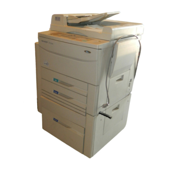
SF-2040
SF-D23
SF-DM11
This document has been published to be used for
after sales service only.
The contents are subject to change without notice.
Advertisement
Table of Contents

Related Manuals for Sharp SF-2040


Summary of Contents for Sharp SF-2040
-
Page 1: Service Manual
SERVICE MANUAL CODE: 00ZSF2040FM/E No.1 SF-2040 MODEL SF-D23 MODEL SF-DM11 MODEL CONTENTS [ 1 ] PRODUCT OUTLINE ........1-1 [ 2 ] PRODUCT SPECIFICATIONS . -
Page 2: Table Of Contents
CONTENTS [ 1 ] PRODUCT OUTLINE ............... . 1-1 General description . - Page 3 (1) SF-2040 ........
- Page 4 9. Toner density sensor level adjustment ........... . . 5-8 A Developing unit level adjustment .
- Page 5 (6) SF-IC11 ................5-25 1 To remove the stopper for the cassette unit.
- Page 6 [ 7 ] ADJUSTMENT ................7-1 Developing Unit .
- Page 7 [ 8 ] Simulation and diagnostics ..............8-1 Simulation .
-
Page 8: 1 ] Product Outline
(1) Compact body 1. General description Use of a front loading paper cassette. The SF-2040 is medium class copier that produces 40 copies per (2) Serviceability and functionality minute. The SF-2040 has all the standard features of medium class copiers to provide high productivity in offices with improved versatility 1 Use of a liquid crystal display with backlight. -
Page 9: 2 ] Product Specifications
[2] PRODUCT SPECIFICATIONS 1. Basic specification (1) Type Desktop (2) Copy method Dry electrostatic copier Sheet, book, three dimensional object (3) Kinds of originals Thickness of original: Maximum 30mm in level with the original cover in use. Weight of original: Maximum 1.8 kg (4 pounds) Maximum original size: A3, Ledger... -
Page 10: Magnification Ratio
52 to 128 g/m (14 to 34 Ibs) (A4 size or under, if above 105 g/m or 28 Ibs) Kind of paper: Standard, Sharp designated paper, OHP Detection size Inch series: Available: Ledger, Legal, Letter, Letter (R), invoice AB series: Available: A3, B4, A4, A4R, A5 2 –... -
Page 11: Developing Method
(11) Developing method Dry, two components magnetic brush method (12) Charge method (–) DC saw-tooth electrode method (13) Transfer method (–) DC Corotron method (14) Separation method AC Corotron method (15) Fusing method Heat roller method (16) Cleaning method Blade method (17) Light source Halogen lamp (18) Blanking areas... -
Page 12: Additional Features
Availability (21) Additional features of feature Overseas: Available when RADF is used. Inhibited when mixed paper feed/ APS: Auto paper selection Overseas: Available when RADF AMS: Auto magnification ratio is used. selection 9mm shift (S → S), with Margin shift DPCM: Dual page copy mode adjustment function DPCM... -
Page 13: Accessories
SEL = English/French packed together. SEEG (BG) = Treated in a kit. Other printed matters: Delivery/installation report (Japan/SEEG), SCA warranty, Warranty registration (SUK), Maintenance card, Counter contract × 2 (Japan) : Retractable (Japan), Fixed (Outside Japan) 2. Consumables SF-2040 supply system (SEC) Name Content Life Product name... - Page 14 Fusing gear × 5 5,000 times × 5 Staple cartridge Staple cartridge SD-LS20 Common to the cartridge for SD-2075. (SD-SC20) × 5 = SD-LS20 SF-2040 supply system (SCA, SCNZ, Middle East, Africa) Name Content Life Product name Package Remark × 1...
-
Page 15: Environmental Requirements
3. Environmental requirements Conditions required for proper operation of the machine, as well as assurance of copy quality, the following are requested. 1 Standard conditions Recommended temperature range at 20 to 25 Centigrade (68 to 77 degrees F) and humidity range at 65 ± 5%RH. 2 Operating conditions Humidity 15˚C... -
Page 16: Sf-A55
[3] OPTIONS SPECIFICATIONS 1. SF-A55 Name Reversing automatic document feeder Original feed system Continuous auto feed Document feed sequence Bottom take-up feeding (Face-up discharge) Document transfer drive Belt drive Orientation of document setting Face up A3 ∼ B5/W letter ∼ Invoice Document size Thin paper mode: 35 ∼... -
Page 17: Sf-D23
4. SF-D23 Name 2-cassette paper feed desk Paper size and capacity 550 sheets of A3, B4, A4, or B5 for each cassette 56 ∼ 80g/m Paper weight Paper transport system Roller transport (center reference) Power source Supplied from the copier. 600mm (W) ×... -
Page 18: External View
[4] COMPONENT IDENTIFICATION 1. External view 11 12 Document holder Exit tray Document cover (optional) Operation panel Document glass Paper clip tray Manual feed tray paper guides Manual feed tray Exit area cover Duplex module or 500-sheet paper Power switch Lower paper tray drawer (optional) Front cover... - Page 19 17 18 Fusing section Transport section open/close lever Photoconductor drum Charger Toner box Toner box lever Roller rotating knob Toner collection container 4 – 2...
-
Page 20: Operation Panel
2. Operation panel SCROLL DISPLAY PROGRAM READY TO COPY. COVERS ERASE MARGIN DUAL PAGE SHIFT COPY INFORMATION INTERRUPT ORIGINAL 8½ x 11 SORTER ORIGINAL TO COPY AUTO IMAGE COPY RATIO CLEAR ALL AUTO PAPER 8¼ x11R 1 0 0 % SELECT (ORIGINALS) SORT... -
Page 21: Internal View
3. Internal view 23 22 #2 mirror #3 mirror #1 mirror Copy lamp Lens unit Main corona unit Blank lamps #6 mirror #4 mirror #5 mirror — Developing tank Resist roller Transfer corona Drum Separation corona Drum separator pawl Cleaner unit Suction unit Suction belts Upper heat roller... -
Page 22: Clutches, Solenoids
4. Clutches, solenoids Signal name Name Function CPFS1 Upper cassette paper feed solenoid For tensioning takeup roller CPFS2 Lower cassette paper feed solenoid For tensioning takeup roller CPFC1 Upper cassette paper feed clutch For actuating paper feed roller CPFC2 Lower cassette paper feed clutch For actuating paper feed roller MPFS Manual paper feed solenoid... -
Page 23: Sensors
5. Sensors Signal name Type Name Output CSWL Microswitch Cover switch, (left) On when closed Transmssive photosensor Paper exit sensor Low when paper passes over P-SW See-saw switch AC power switch — MHPS Transmissive photosensor Mirror home position sensor High when scanner at home postion CSWF Microswitch Cover switch, (front) -
Page 24: Motors
6. Motors Signal name Name Type Function Main motor DC, brushless Driving copier and ADU option Mirror motor DC, brushless Driving optical system mirror bases A and B Lens motor DC, stepping Driving optical lens #4/5 mirror base motor DC, stepping Driving optical mirror base C Toner motor DC, synchronous... -
Page 25: Board List
7. Board list Name Type Function Main PWB Japan/Export Primary control of copier functions Operation PWB Common Display AC PWB Japan/Export, 100V/200V Supplying AC power Blank lamp PWB Common Controlling blank lamps Original sensing light emitting PWB Japan Sensing original size Original sensor light receive PWB Japan Sensing original size... -
Page 26: Duplex Copy Tray
8. Duplex copy tray Signal name Type Name Output APHPS2 Transimissive photosensor ADU rear plate home position sensor Low when at home position DPPD1 Transimissive photosensor ADU paper transport sensor-1 High when paper passes over APHPS1 Transimissive photosensor ADU alignment plate home position sensor Low when over home position DPPD2 Transimissive photosensor... -
Page 27: Desk Unit (Sf-D23)
9. Desk unit (SF-D23) 4 – 10... - Page 28 A. Sensors and switches Signal name Name Type Function/operation Contact/output SIZESW Size switch Slide switch Size (A4, B5, Letter) selection — Front loading F/LSW Microswitch Desk open/close detection H level when open. open/close switch Cassette 2 original presence H level when paper is DPE2 Empty sensor Reflection type sensor...
-
Page 29: 5 ] Installation
5. Be sure to allow the required space around the machine for ser- [5] INSTALLATION vicing and proper ventilation. 11-13/16" (30cm) A. Installing conditions 12/8" 00-13/16" To ensure safety and proper machine performance, please note the (60cm) (30cm) following before initial installation and whenever the machine is to be relocated. -
Page 30: Installation Procedure
5 Hold the fuser unit hand carry strap and remove the fuser unit. B. Installation procedure (1) SF-2040 Hand hold strap 1. Releasing optical locks Front panel band A. Removing the #2/3 mirror unit lock Paper exit Unfasten the screw that holds the #2/3 mirror unit on the left side of Screws the machine. -
Page 31: D Installing The Fusing Unit
2 Remove the CL springs which are fixed to the front and the rear D. Installing the fusing unit side of the fusing unit with adhesive tape. Insert the locator pin under the fuser unit into slot. Gently push fuser unit all the way in. -
Page 32: B Clean The Transfer/Separation Corona Wires
3 Very carefully clean the top of the electrode using the repeat this 2 Unhook the section A of the separation corona guide, slide the procedure a few times. separation corona in the direction of the arrow, and remove the separation corona guide from the corona housing. -
Page 33: Setting Up The Upper Paper Cassette
E. Set the size detect spacer 5. Setting up the upper paper cassette Change the position of the size detect spacer. Move the spacer to the A. Remove the packing screw of the cassette. appropriate positions. Pull out the cassette drawer by lifting while pulling out drawer. Remove the one packing screw that secures the paper tension plate (Ex) A3 setting Size detect spacer... -
Page 34: G Set The Cassette
G. Set the cassette B. Change the size using the side plates F and R. (set to A3 position at the factory.) Hold up both sides of the cassette from back and insert it along the guide rails. Set the plates into the appropriate positions and secure wach plate with two screws. -
Page 35: E Change The Paper Size Indication Plate
3 Slide the developing unit lock lever in the arrow direction to E. Change the paper size indication plate release lock, and hold the toner box lever and pull out the Remove the paper size indication plate. Install the plates so the size developing unit until it stops. -
Page 36: Setting Developing Unit
8. Setting the developing unit 9. Toner density sensor level adjustment Turn on the power switch of the copier body. A. Supplying developer A. Developing unit level adjustment 1 Remove the 5P connector which is connecting the toner hopper and the developing unit. 1 Perform the key operations of simulation 25. -
Page 37: Label Attachment
5 Move the toner cartridge in the arrow direction until it stops. 9 Push the toner box slowly to the original position, and lift the toner box lever. Toner box lever 6 While holding the toner cartridge, pull the seal to supply toner. Toner supply is completed with the above procedure. -
Page 38: Sf-A55
Fit the holes in the hinges of the ADF onto the ADF mounting screws (2) SF-A55 and secure the ADF with the two ADF securing screws. ADF securing screw ADF mounting screw ADF securing screw ADF tray 2. Adjust the angle of ADF. Loosen the two fixed screws for the angle adjusting panel which are ADF mounting screws ADF securing screws... -
Page 39: Connect The Adf Tray Connector
3. Connect the ADF connector. Plug the copier into a grounded outlet and turn the power switch on. Remove the connector cover from the copier’s rear cabinet panel. Next, connect the ADF connector to the connector on the copier. Then, follow the procedure below. 6. -
Page 40: Original Lead Edge Position Adjustment
H Fig. 1 (3) If the original were to override the stopper, enter an optimum Move the tray in the direction A and secure it with the two mount- value to move it to the glass side. ing screws. Make sure that it is centered properly. Original Stopper Fig.1... -
Page 41: Model
Be sure that you have plenty of room around the copier for work space. Rail mounting plate: 1 Green label: 1 Support guide: 1 1.0m Remove the securing fixtures and attach the caster spacers. When performed on the skid. Remove the securing fixtures (2). Securing fixtures Sorter protection mat: 1 Stapling location label A: 1... -
Page 42: Mounting Of The Staple Sorter Onto The Copier
When not performed on the skid Unplug the copier’s power cord before carrying out the following procedure. Open the sorter protection mat, as shown in the figure, and position it against the sorter’s casters. Lay the sorter down on the protection mat. - Page 43 4. Attach the rail to the sorter. 7. Confirm that the staple sorter can be attached and detached correctly. Insert the rail into the rail mounting anchor, on the bottom of the sorter, and attach them with the 2 rail screws A (M4 x 6) and 1 rail 1 Latch and unlatch the staple sorter from the copier to confirm that screw B (M4 x 6).
- Page 44 RADF 9. Attach the sorter connectors. Loosely screw in one of the two supplied bracket screws in the posi- tion shown in the figure. Hook the bottom of the bracket in place over this screw, then insert the other screw into the top of the bracket and tighten both screws securely.
-
Page 45: Staple Sorter Operation Check
• If the mode is being set for a combination of options, add up the 3. Reinsert the staple cartridge. numerical values of the options to be set (see the table below) and Push the staple cartridge in horizontally until it clicks securely into input the total sum. - Page 46 This completes the staple sorter installation. 5. Reinstall the staple unit. Reinstall the staple unit in its original location using the mounting If staples have become jammed. screw to secure it in place. Then close the stapler cover. 1. Remove the stapler unit. Open the stapler cover and remove the mounting screw securing the Staple unit unit in place.
-
Page 47: Sf-S15 (20-Bin Sorter)
(4) SF-S15 (20-Bin Sorter) 2. Mount the sorter seat to the desk. Remove the two cut-outs in the cabinet panel on the left side of the desk. Secure the two sorter seat mounting screws A to the desk. Next, hook the sorter seat onto the two sorter seat mounting screws A which were secured to the desk, and then use the one sorter seat mounting screw B to secure the sorter seat mounting fixiture as shown. -
Page 48: Place The Sorter On The Sorter Seat
4. Place the sorter on the sorter seat. 6. Connect the sorter connectors. While holding the handle, place the sorter on the sorter seat’s guide Use the two bracket mounting screws to secure the bracket attached rails and push it gently as far back as it will go. to the sorter harness to the frame of the copier. -
Page 49: Adjust The Clearance Between The Sorter And The Copier
9. Adjust the clearance between the sorter and the (5) SF-D23 copier. Push the sorter gently against the copier’s left cabinet panel. The clearance spacers attached to the back of the sorter will determine the standard clearance between the sorter and the copier. Turn the adjustment knobs on the sorter seat to adjust the clearance so that the spacers are touching the copier. -
Page 50: Secure The Copier To The Desk
2. Secure the copier to the desk. 5. Remount the rear coverlet of the copier. Use the included four mounting screws to securethe copier to the Return the rear coverlet to its original position and use its mounting desk. screw to mount it. •... -
Page 51: Pull Out The Cassette
7. Pull out the cassette. 9. Adjust the side guides Grasp the cassette by the handle and pull it out gently as far as it will Remove the mounting screws (one per guide) holding the right and left paper side guides in place. Use the mounting screws to secure the right and left paper size guides (one screw per guide) in the positions corresponding to the paper size which has been set. -
Page 52: Set The Paper Size Switch
10. Set the paper size switch 12. Place the paper in the cassette. Set the paper size switch to match the paper size which has been Place paper in the right paper cassette.When doing this, do not stack set. the paper higher than the maximum height line indicated on the cas- sette. -
Page 53: Adjust Any Center Misalignment
• If the mode is to be set in combination with other options, use the When off center as shown in fig. 1 table shown below to add up the total of the setting values for all Move the center adjuster in direction A and secure it with the two the peripheral devices to be set, and set that total value. -
Page 54: To Change The Size Setting Of Side Plate F And Side Plate R
3. To change the size position of the rear end plate. Cassette size label Remove the rear end plate from its rear storage place, and insert this AB system into the cassette main unit for the desired size. ⁄ ⁄ When you switch the size to A5 or 8 , fix this plate to the rotary plate by using the screw that is attached to the rear end... -
Page 55: To Change The Paper Size Indication Plate
5. To stick the cassette size labels. (7) SF-DM11 Stick the cassette size labels that indicate and correspond to the desired size on the marked positions for sticking (2 positions). If you change the size to A5 or 8-1/2 x 5-1/2, take out the paper size indication plateand stick the size label on the indication plate and align the sticking line as shown in the figure. -
Page 56: To Install The Adu Drive Unit
• When a container fixing lever is not installed 2. To install the ADU drive unit. Open the storage cover for the toner collecting container, then Remove the connector, that has been inserted temporarily to the remove the toner collecting container by pulling out and pressing connector near the copier main unit for connecting with ADU drive down on it at the same time. -
Page 57: To Install The Toner Collecting Container
8. To install the toner collecting container. When the matching guide is aligned properly, perform step 10 in the Installation Procedure. • When a container fixing lever is installed Reinstall the toner collecting container that has been removed in step When the matching guide is not aligned properly, 4, restore the container fixing lever, and close the storage cover for perform the following Procedure to adjust the... -
Page 58: Sf-Cm11
* In case of Fig. 1 Be sure to unplug the copier and install the unit as Move the front cabinet to the direction A, tighten the fixing screws follows: a (2 pcs.) and b (2 pcs.) in this order, and make a copy again to check that there is no center dislocation. -
Page 59: Remount The Rear Cabinet Panel Onto The Desk
3. Remount the rear cabinet panel onto the desk. 6. Install the paper feed unit. Return the rear cabinet panel that has been removed in step 1 and Fit the groove in the paper feed unit into the guide rail, and then, secure it in its original position using the two mounting screws. -
Page 60: Position The Rear Edge Plate
9. Position the rear edge plate. 11. Change the paper size indicator. Remove the rear edge plate from its storage slot and fit it into the Remove the paper size indicator and reinsert it to show the paper cassette to set the desired paper size. size for which the cassette has been set in the paper size indicator window. -
Page 61: Install The Paper Cassette
14. Install the paper cassette. 17. Adjust any center misalignment. Lift the rear sides of the paper cassette and insert the both right of Make a copy, and if there is any center misalignment such as that guides into the Copier by fitting them to the guide rails as shown in shown in Fig. -
Page 62: 6 ] Disassembly And Reassembly
[6] DISASSEMBLY AND REASSEMBLY 1. Process unit Discharge Drum Toner receiver BL PWB UN Cleaning blade lamp unit Remove the process cover (1 screw) and remove the process unit from the copier (3 screws). Detach the clam shell mechanism (4 screws). Loosen two blue screws that hold the drum Unfasten the blank Remove the cleaning... - Page 63 6 – 2...
-
Page 64: Manual Feed Multicopy Unit
2. Manual feed multicopy unit Paper feed Counter roller Takeup roller Spring clutch, small Spring clutch, large roller Remove the right side panel of the copier (3 screws). Remove the manual feed multicopy unit (4 screws, 2 connectors). Remove the partition Remove the reverse Remove the manual feed multicopy solenoid (2 screws). - Page 65 6 – 4...
-
Page 66: Paper Feed Unit
3. Paper feed unit Paper feed Takeup roller Counter roller Solenoid roller Unfasten the harness of the spring clutch. Remove the tension spring. Remove the spring. Remove the manually set Remove the manually set E-ring. Remove the solenoid lever. E-ring. Remove the solenoid Move the clutch shaft to the location where the pickup roller lever Move the shaft, including the... - Page 67 6 – 6...
-
Page 68: Transport Baseplate Unit
4. Transport baseplate unit Paper stop Paper stop Suction unit transfer belt roller clutch 10 Remove the connecting plate 5 in Fig. F . (2 screws) Remove the transport baseplate from the machine 11 Remove the stopper and the (4 screws on front, 2 on rear, 2 connectors). 22T gear. - Page 69 6 – 8...
-
Page 70: Fuser Unit
5. Fuser unit Upper/lower Upper/lower Upper cleaning Heater lamp heat roller separation pawls roller Remove the fuser cover (2 screws). Remove the cleaning roller springs on the Unfasten the heater lamp connectors on both sides. front and the rear sides. Unfasten the thermistor and thermostat connectors. - Page 71 6 – 10...
-
Page 72: Duplex Copy Unit
6. Duplex copy unit Paper feed Counter Takeup roller roller roller Remove the double side copy tray. Remove the front cover (2 screws). Unfasten two connectors. Remove the pivot holding plate screw (one each on both sides). Remove the upper and transport paper guides from ADU. Remove the front and rear side two Remove the clutch retaining plate Remove the clutch stopper plate... - Page 73 6 – 12...
-
Page 74: Rear Frame Side Major Components
7. Rear frame side major components Paper feed Variable paper Main drive unit (belt) drive unit speed unit Remove the rear panel (4 screws). Remove the main PWB connectors (13 connectors). Remove the main PWB unit from the copier (1 screw). Remove the paper feed drive unit (4 screws). - Page 75 6 – 14...
- Page 76 DC power Paper exit gate AC power supply PWB supply PWB solenoid Remove the rear panel of the copier (6 screws). Remove the rear side screw of the left side panel (1 screw). Remove the AC power supply board (2 screws, 6 connectors). Remove the DC power supply PWB (5 screws, 1 connector).
-
Page 77: Operation Panel Unit And Document Size Sensor Board
8. Operation panel unit and document size sensor board (light receive side) Operation Document size sensor LCD unit panel board light receive side Remove the LCD control PWB from the operation panel Open the front panel. unit. (3 screws, 1 connector) Remove the LCD control PWB mounting angle from the Remove the middle panel (5 screws). - Page 78 Volume PWB 6 – 17...
-
Page 79: Optical Unit
9. Optical unit Copy lamp Copy lamp unit #2/3 mirror base unit #4/5 mirror base unit Remove the original guides (L, R) and remove the table glass (two each screws). Move the copy lamp unit to the cut in the Remove the operation panel. - Page 80 6 – 19...
- Page 81 Mirror base wire stretching (Preliminary checks) Check the stop position of the wire winding pulley. Visually check that the wire grooves of the front/rear wire winding (Front) (Rear) pulleys are at the same level. If there is a substantial discrepancy between the two, loosen the two setscrews which are fixing the pulleys and adjust the pulley positions.
- Page 82 Mirror base wire tension adjustment 1 Manually turn the mirror base drive pulley to shift mirror base B which is at the mirror base positioning plate 20 to 30mm to the paper exit side. 2 Turn the mirror base wire tension adjustment screw clockwise to apply tension to the wire until the wire tension spring edge makes contact with the projection of mirror base B.
-
Page 83: Developing Unit
[7] ADJUSTMENTS 1. Developing Unit Tool: UKOGM0075CSZZ (Feeler gauge) (1) Clearance Adjustment of Developing Doctor 0.03 0.525 Blade 0.03 1 Remove the 4 screws and the 5-pin connector which connect the developer tank to the toner hopper, and pull out the developer tank. -
Page 84: Developing Bias Adjustment
(3) Developing Bias Adjustment 1 Set the measuring range of the digital multimeter to 300 Vdc or more. 2 Apply the probes to the developing bias output check pin (CP-B) and the chassis(GND) of the high voltage unit. 3 Perform Simulation 8-1. (The developing bias voltage is output for 30 seconds. -
Page 85: Processing Unit
2. Processing Unit (1) Adjustment of Blank Lamp Position 1 Check that the center deviation is 2.0mm or less. (If the center Backward deviation is more than 2.0 mm, correct it). 2 Set an A3(11x17)-size blank original on the original table, and with the original cover opened, make a reduced (x 0.64) copy using an A3 (11 x 17) paper. -
Page 86: Adjusting The Transfer Charger Current
B. Adjusting the Transfer Charger Current 1 Remove the developing unit, transfer/separation charger unit, main charger unit and waste toner bottle from the machine. 2 Remove the processing unit from the machine. When removing (attaching) the processing unit, do not grasp the toner feed pipe. -
Page 87: Checking The Electrostatic Main Charger Current
C. Checking the Electrostatic Main Charger Current The drum current difference(balance) between the sides of front and rear frame is checked. 1 Perform steps. 2 Clean the saw-tooth plate of the main charger with polystyrene foam and attach the main charger to the machine. (Do not attach the transfer/separation charger). -
Page 88: Adjusting The Separation Charger Output
E. Adjusting the Separation Charger Output 1 Attach the developing unit and the drum holder unit to the machine and turn on the machine. (Do not use the electrode sheet). 2 Attach the separation charger unit and drum holder unit to the machine. -
Page 89: Optical System
3. Optical System The optical system must be adjusted according to the following flowchart: Check the following preset values depending on the focal length of lens (lens number): • Reference position of 4. and 5. mirror Reference position of lens. Simulation 48-01 •... -
Page 90: Adjusting The Reference Position Of Lens
(1) Adjusting the Reference Position of Lens A reference value depending on lens characteristics must be input for adjusting the reference position of lens. (This value determines the home position of lens). (Procedure) Perform Simulation 48-01 =↵ . C → =↵ → →... -
Page 91: Adjusting The Resolution
5 Perform Simulation 48-01 =↵ . C → =↵ → 0/◊ → =↵ → → 8 → PSW → 1 → PSW causes a preset value of longitudinal magnifica- tion to be indicated. 6 Determine a preset value of longitudinal magnification according to the following expression: 100 mm-scale (original) Preset value of longitudinal magnification = previous preset... -
Page 92: Adjusting The Lateral Magnification
(5) Adjusting the Lateral Magnification The lateral magnification should be adjusted in the following cases: • When the main PWB is replaced. • When the RAM in the main PWB is replaced. Scale • When self diag U2 occurs. • When the mirror motor is replaced. - Page 93 Lens display value Correction reference value Lens characteristics Lens display No. 4/5 mirror Vertical input value value focus adjustment magnification ratio 26-08 (45MB) adjustment No. 4/5 mirror 48-01 48-01- characteristics input value 26-09 +8.0 +4.0 +7.8 ~ 7.9 +7.6 ~ 7.85 +7.6 ~ 7.7 +3.8 ~ 3.9 +7.4 ~ 7.5...
-
Page 94: Correcting The Longitudinal Distortion
Lens display value Correction reference value Lens characteristics Lens display No. 4/5 mirror Vertical input value value focus adjustment magnification ratio 26-08 (45MB) adjustment No. 4/5 mirror 48-01 48-01- characteristics input value 26-09 –2.5 ~ 2.4 –1.3 ~ 1.2 –2.7 ~ 2.6 –2.8 ~ 1.9 –2.9 ~ 2.8 –1.5 ~ 1.4... -
Page 95: Correcting The Lateral Distortion
If the width of the front end solid (La) is equal to that of the rear end solid (Lb), no adjustment is required. Otherwise, follow the steps 4 to 7 described below: 4 Loosen screws securing the mirror base driving pulley on the rear frame side. -
Page 96: Adjusting The Center Deviation
If La=Lb and Lc=Ld, no adjustment is required. If La>Lb(Lc<Ld), rotate the eccentric roller in one direction to raise the front frame side of the 4. and 5. mirror base unit. If La<Lb(Lc>Ld), rotate the eccentric roller in the other direction to lower the front frame side of the 4. -
Page 97: Adjusting The Copy
Eg. If the copy is as shown in the figure, move the exposure con- Exposure trol plate a in the B direction to achieve the exposure balance. insufficient Paper discharge direction Half-tone copy (11) Adjusting the Copy Lead Edge Simulation 50-01 or 50-02 allows the copy adjustment. Simulation No. - Page 98 • L1: Lead edge deviation at 200% magnification • L2: Lead edge deviation at 100% magnification • RRC-A = 4.7222 x (L1 – L2) • RRC-B = 7.2202 x L2 – 3.6101 x L1 5 Using the ten keys, input the values of RRC-A and RRC-B given by the expressions shown above.
- Page 99 G Take a full-size copy and check if the image loss and the void area meet the following standards: (Standard value) Void area 1~4mm Image loss: 0 ~ 4 mm Void area: 1 ~ 4 mm H Press the clear key to clear Simulation 50-01. Note: After changing the RRC-A and RRC-B settings, al- Scale image ways adjust the void area of copy end.
-
Page 100: Adjustment Of Copy Density
(2) Initial setting of TSM mode (User adjustment) 4. Adjustment of Copy Density 1 Execute simulation 26-18. 1. When must the copy density be adjusted ? 0: Cancel, 1: Setting • When doing maintenance; 2 Select "0" with the 10 key pad. •... -
Page 101: Setting Of Test Chart
0.5 1.9 0 DENSITY No. Copied KODAK GRAY Not copied SCALE SHARP CORPORATION C. Adjusting the TSM mode MADE IN JAPAN 1 Press key to highlight "TS1:". 2 Perform adjustments of TS1 and TS5 similarly to ME1 and (6) Adjustment of copy density ME5. - Page 102 E. Adjusting the auto(normal) mode 1 Press key to highlight AE1. 2 Enter "0" for AE1. 3 Press key to highlight AE5. 4 Make a copy. Check that the "3" of UKOG-0162FCZZ (or 0.2 of UGOG- 0089CSZZ) has slightly copied. If the above condition is not met, readjust as follows: <When light>...
- Page 103 UKOG-0162FCZZ DENSITY No. UKOG-0089CSZZ 0.5 1.9 DENSITY No. KODAK GRAY SCALE SHARP CORPORATION MADE IN JAPAN (6) Adjustment of copy density A. Adjusting the developing bias output –300 V (manual exposure 1) Perform Simulation 8-01 B. Adjusting the manual-exposure copy density...
- Page 104 Item Description PE 5 Slightly copied Not copied E. Adjusting the auto-exposure copy density (1) Normal mode AE 1 Input "0" AE 5 Slightly copied Not copied (2) TSM mode AE 1 Input "0" AE 2 Slightly copied Not copied 7 –...
-
Page 105: Adjustments Relating To Process Control
• Turn on the power. 6. Adjustments relating to process control (1) Execute simulation No. 24-7 drum film wear correction counter (The adjustment procedures differ according to the state of service reset. maintenance.) (2) Execute simulation No. 25-2 toner density reference value set- ting A. - Page 106 (Trouble codes and countermeasures) Trouble code Sub code Content Possible cause Countermeasure Image exposure sensor error Dirt on the image density sensor (ID) Clean the image density sensor and Photoconductor surface its peripheral. Use soft cloth reflection detection error immersed in water or alcohol to clean Copier operation halt when the sensor surface.
-
Page 107: Simulation
*2: Further operation may be needed depending on the kind of [8] Simulation and diagnostics simulation. *3: One of the next methods is required to cancel the simulation as it varies according to the simulation. The machine then starts 1. Simulation from the state immediately after power on. - Page 108 Sim. NO Sim. SUB Description Optical system mirror scanning check Optical system sensor state display Lens movement operation check Lens aging RADF aging RADF sensor state display Motor A forward rotation Motor A reverse rotation Motor B forward rotation Motor B reverse rotation RADF individual load operation check Belt clutch Paper feed solenoid...
- Page 109 Sim. NO Sim. SUB Description Total jam counter display Total counter display Developer counter display Developer preset cycle counter display RADF counter display ADU counter display Staple counter display Developer adjustment time display Drum adjustment time display Key operator code display ROM version display Trouble memory display Cassette paper feed counter display...
- Page 110 Main code Sub code Description Ref. Page This is the test command used to test the optical system. The mirror base automatically starts to scan. (1) With depression of the PAUSE key, the control moves from the test command mode to be ready to execute it.
- Page 111 Main code Sub code Description Ref. Page This is the test command used to test the sensors in the sorter. On/off state of sensors can be manually tested. When the sensor turns on, the display reverses. Paper entry sense (non-sort) Indexer upper limit sense Sorter set sense PES/SPID...
- Page 112 Main code Sub code Description Ref. Page First tray size switch check Second tray size switch check Transport motor activation check Lift up motor rotation check (First tray) Lift up motor rotation check (Second tray Stack1) Lift up motor rotation check (Second tray Stack2) Transport clutch activation check Paper feed solenoid activation check (First tray) Paper feed clutch activation check (First tray)
- Page 113 Main code Sub code Description Ref. Page Developing bias voltage output. After delivering the output, the machine automatically goes into the sub [7]-2(3) code input wait state. This is the test command used to check the developing bias voltage. The developing bias voltage is turned on for 30 seconds.
- Page 114 Main code Sub code Description Ref. Page — Toner motor activation Used to check the toner motor activation. — Trouble code cancellation This is the test command used to cancel other than the "U2" trouble (H2, H3, H4). After the trouble has been removed, the test command terminates.
- Page 115 Main code Sub code Description Ref. Page ° Total misfeed counter display ° Total counter display This counter is used to show the total copy number of the machine. ° Developer counter display The contents of the copy number counter of the installed developing unit is displayed. °...
- Page 116 Main code Sub code Description Ref. Page Option unit setup • Used to set up option unit. 1 When the test command is executed, the presently stored machine setup code is displayed with the READY lamp turned on. 2 After the READY lamp has turned on, enter an appropriate setup code on the keypad and press the PRINT switch.
- Page 117 Main code Sub code Description Ref. Page Lens characteristics entry (at a time of lens replacement) [7]-10-(6) Because each lens has a variance in focal distance, the lens moving distance in any zoom mode must correspond with the focal distance of the lens. The zoom ratio varies proportionate to the variance of the lens focal distance.
- Page 118 Main code Sub code Description Ref. Page Correction mode setting [+ 1] Process control correction enable [+ 2] Optical dirt correction enable [+ 4] Drum layer wear correction enable [+10] Toner control A correction valid [+20] Toner control B correction valid Note: When all are "Enable,"...
- Page 119 Main code Sub code Description Ref. Page Compulsory execution of process control SIMULATION No.44-6 Process control execution : **** : *** NORMAL PATCH1 : **** : *** BASE1 : **** : *** PHOTO PATCH2 : *** : *** GB ADJUST BASE2 : *** : ***...
- Page 120 Main code Sub code Description Ref. Page Process control data display SIMULATION No.44-9 Process control data display : **** : *** NORMAL PATCH1 : **** : *** BASE1 : **** : *** PHOTO PATCH2 : *** : *** GB ADJUST BASE2 : *** : ***...
- Page 121 Main code Sub code Description Ref. Page ° AE sensor characteristics measurement [7]-18-(3) AE sensor output characteristics memory (1) AE sensor output characteristics input Press the C → =↵ → → =↵ → 4 → → PSW keys. The mirror base is ini- tialized, scans about 10cm, then stops.
- Page 122 Main code Sub code Description Ref. Page ° Resist roller adjustments Used to set the on timing of the paper feed roller (rate of buckle in the paper caused by the resist roller). When the test command is executed, the manual feed mode is automatically established. Change the manual feed mode resisting rate, cassette paper feed resist rate, and ADU paper feed resist rate independantly.
-
Page 123: Trouble Codes List
Main code Sub code Description Ref. Page ° RADF and ADF timing sensor adjustment Used to adjust the RADF timing sensor. When this simulation is executed, the RADF timing sensor is adjusted and the adjustment value is displayed. ° RADF and ADF repulsion sensor adjustment Used to adjust the RADF repulsion sensor. -
Page 124: Key Operator Program
Display codes other than trouble Trouble codes Sub code Operation — Door open/DV unit uninstalled — Personal counter uninstalled/auditor code input waiting — Copy inhibit command is received from the host when installing PC/Modem. (Key operator program) The list below shows all key operator programs. These programs can be used only when the key operator code in inputted at the beginning. Program Program name Function... -
Page 125: Maintenance And Others
[9] MAINTENANCE AND OTHERS The maintenance of the SF-2040 should be performed every 80K and 120K cycles. <Remarks> = lubrication, F=cleaning, v = adjustment, b=replacement/mounting, k=repositioning, =check (cleaning, replacement and/or adjustment if necessary) * Toner consumption and waste toner bottle replacement cycle are replacement cycle when using the reference chart (6% original). -
Page 126: Counters And Simulations Related To Maintenance
2. Counters and simulation related to maintenance (1) List of counters and test commands related to maintenance Test Command Description Function Main code Sub code Clear the maintenance counter The contents of the counter is cleared to zero. Set the maintenance cycle Code Maintenance cycle 0 .. -
Page 127: Alarm Message
(2) Alarm message When any trouble occurs which makes it unable to start or continue copying, one of the following messages is displayed. When the trouble is cancelled, the message is cleared and the machine is automatically reset. Alarm message Troubles which can be Troubles which reguire the key Troubles which reguire service... - Page 128 Copying/standby Stapler empty is sensed Copy possible Staple mode specifided "Replace the staple unit cartridge. Open the sorter cover and follow the direction." Copy unable Staple mode is canceled Stapler needle (New cartridge insertion) Copying/standby Waste toner bottle full is sensed "Replace the waste toner bottle"...
-
Page 129: Setting The Copy Counter Mode
Copying/standby Duplex tray trouble is sensed Copy possible Duplex mode is specifided "Duplex copy trouble function." Copy unable Duplex mode is canceled Use key operator program No.75 to inhibit automatic duplex copy Cancel: If the power is turned on/off without canceling the error the machine goes into the ready mode but the message is displayed again when the duplex mode is selected 7 , 8 Use of the function or the unit is inhibited... -
Page 130: Oil/Grease Points
(3) Gears of paper-feed driving unit 4. Oil/Grease Points (4) Fusing unit driving gears (1) Gear of main driving unit (5) Paper exit roller driving gears (2) Gears of variable-speed paper-feed unit 9 – 6... -
Page 131: Paper-Feed Torque Limiter 500-Sheet Cassette Brake Spring
(6) Paper-feed torque limiter 500-sheet cassette brake spring Torque limiter 500-sheet cassette brake spring (7) Optical rail Note 1: Grease (Molycoat (UKOG-0062FCZZ) or White Molycoat (UKOG-0158FCZZ) ) must be applied to the correct grease points of each gear. Do not use too much grease. Note 2: No grease shall be applied inside the gear of the magnetic clutch.